MGC120 Petrol Genset Controller User Manual
MGC120 Petrol Genset Controller Version 1.2 2019-02-22 Page 17 of 20
10 TYPICAL APPLICATION
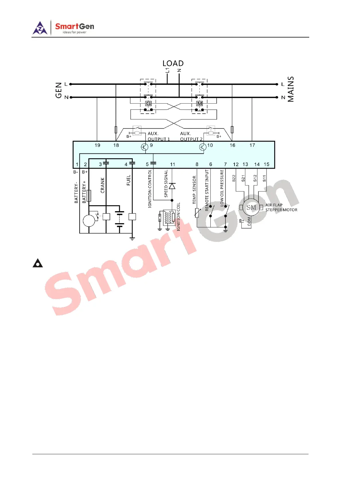
Fig. 5 MGC120 Typical Application Diagram 1
Notes:
1) S11、S12、S21、S22 are separately connected with orange wire, pink wire, yellow wire, and blue wire, and
stepper motor COM (red wire) shall be connected with the battery positive.
2) Terminal 11 must be connected in series with diode. Diode capacity shall be over 1A, and reverse
pressure-standing value shall be over 1000V.
3) The maximum incoming current for programmable output 1 and output 2 shall be 1A.