-19-
No.EX##-OMN0036
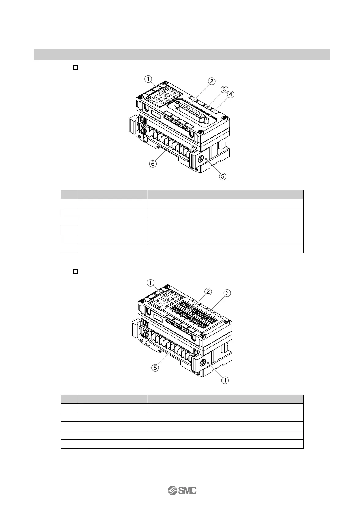
•EX600-DX E
No. Description Function
1 Status display LED Displays the status of the unit.
2 Connector (Input) Connector for input device.
3 Marker groove Groove to mount a marker.
4 Lock screw Fixes D-sub connector. (No.4-40 UNC)
5 Joint bracket Bracket for joining to adjacent units.
6 Unit connector (Plug) Transmits signals and power supplies to adjacent units.
•EX600-DX F
No. Description Function
1 Status display LED Displays the status of the unit.
2 Connector (Input) Connector for input device.
3 Marker groove Groove to mount a marker.
4 Joint bracket Bracket for joining to adjacent units.
5 Unit connector (Plug) Transmits signals and power supplies to adjacent units.
 Loading...


