- 29 -
Operating procedure and input / output signals for each operation
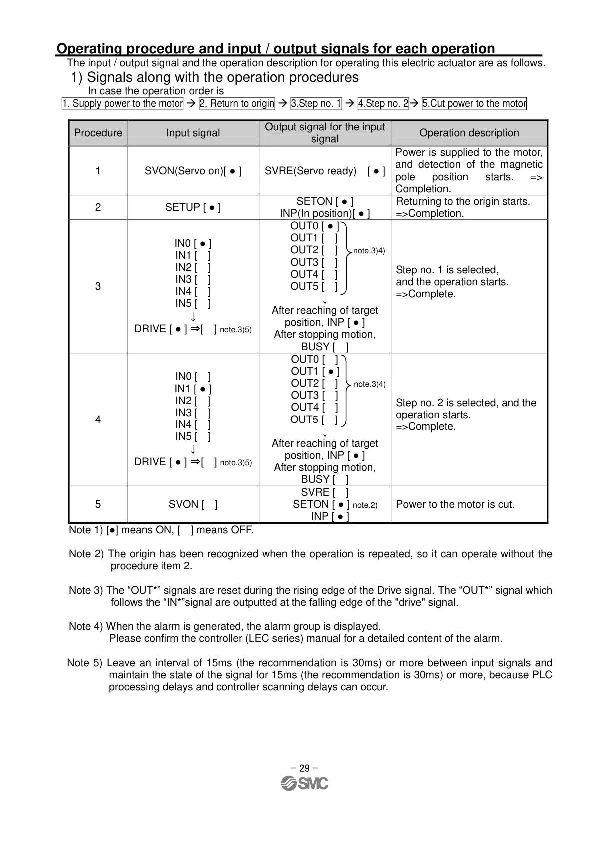
The input / output signal and the operation description for operating this electric actuator are as follows.
1) Signals along with the operation procedures
In case the operation order is
1. Supply power to the motor
2. Return to origin
3.Step no. 1
4.Step no. 2
5.Cut power to the motor
Output signal for the input
signal
Power is supplied to the motor,
and detection of the magnetic
pole position starts. =>
Completion.
SETON [ ● ]
INP(In position)[ ● ]
Returning to the origin starts.
=>Completion.
IN0 [ ● ]
IN1 [ ]
IN2 [ ]
IN3 [ ]
IN4 [ ]
IN5 [ ]
↓
DRIVE [ ● ] ⇒[ ] note.3)5)
OUT0 [ ● ]
OUT1 [ ]
OUT2 [ ] note.3)4)
OUT3 [ ]
OUT4 [ ]
OUT5 [ ]
↓
After reaching of target
position, INP [ ● ]
After stopping motion,
BUSY [ ]
Step no. 1 is selected,
and the operation starts.
=>Complete.
IN0 [ ]
IN1 [ ● ]
IN2 [ ]
IN3 [ ]
IN4 [ ]
IN5 [ ]
↓
DRIVE [ ● ] ⇒[ ] note.3)5)
OUT0 [ ]
OUT1 [ ● ]
OUT2 [ ] note.3)4)
OUT3 [ ]
OUT4 [ ]
OUT5 [ ]
↓
After reaching of target
position, INP [ ● ]
After stopping motion,
BUSY [ ]
Step no. 2 is selected, and the
operation starts.
=>Complete.
SVRE [ ]
SETON [ ● ] note.2)
INP [ ● ]
Power to the motor is cut.
Note 1) [●] means ON, [ ] means OFF.
Note 2) The origin has been recognized when the operation is repeated, so it can operate without the
procedure item 2.
Note 3) The “OUT*” signals are reset during the rising edge of the Drive signal. The “OUT*” signal which
follows the “IN*”signal are outputted at the falling edge of the "drive" signal.
Note 4) When the alarm is generated, the alarm group is displayed.
Please confirm the controller (LEC series) manual for a detailed content of the alarm.
Note 5) Leave an interval of 15ms (the recommendation is 30ms) or more between input signals and
maintain the state of the signal for 15ms (the recommendation is 30ms) or more, because PLC
processing delays and controller scanning delays can occur.
2021-05-2010:32
DW913599
 Loading...


