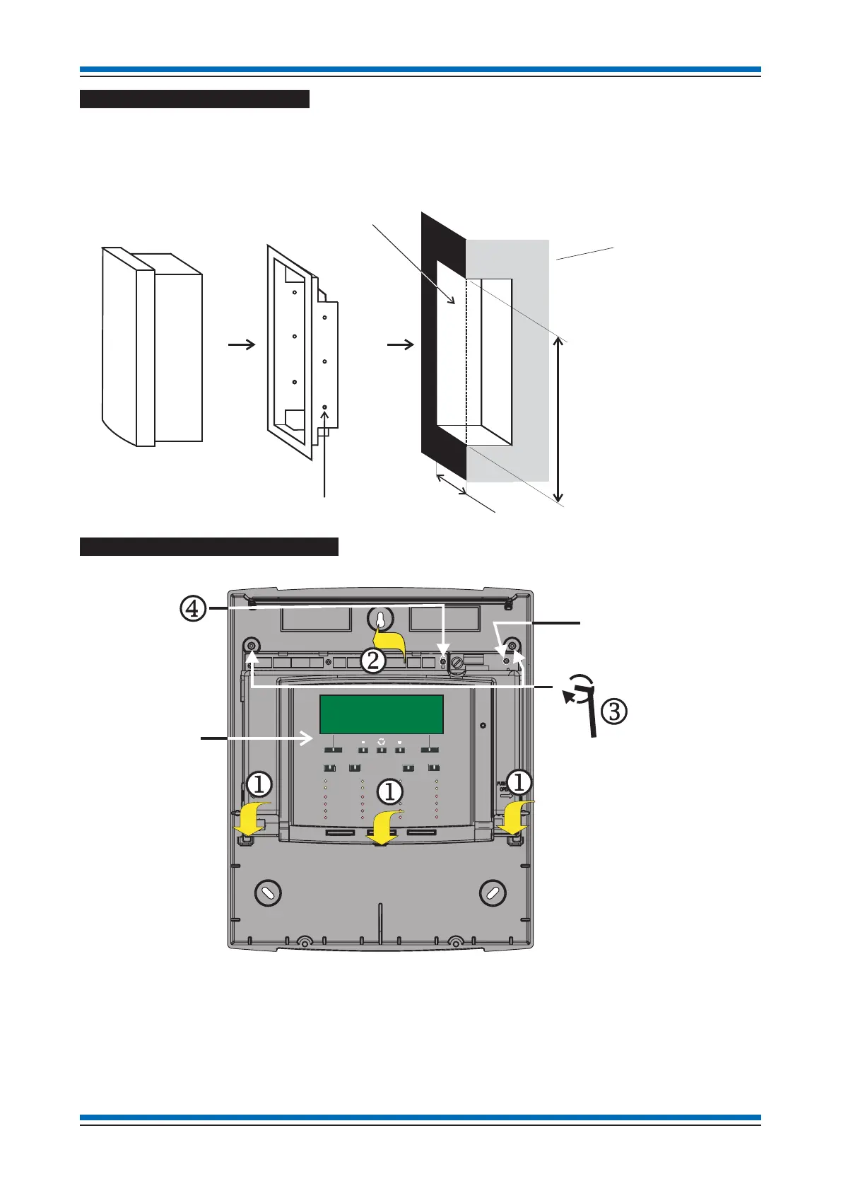
Flush Mounting the backbox
The control panel may be flush mounted using a flush surround SENTRI1-FLUSH.
a Cut out an aperture in the wall to allow the flush surround to be fitted, see diagram for dimension of the aperture.
b Using the fixing holes on the flush surround, secure it into the aperture side walls.
c Route the cables through the cable entry points into the panel and at the same time insert the panel into the flush surround.
d Fit the panel back box to the flush surround using the 3-off 5mm screws not supplied with the flush surround.
Refitting the electronics module
Locate the three tabs of the electronic module j into the backbox and close the upper part k of the module into the backbox and
then secure the assembly by tightening the two captive screws
l using the allen key. Ensure the two PCB fixing-screws m that
provides earth bonding are securely fitted and are not loose.
Installation instructions
16
Control Panel
Cross section of
the wall to which
the panel is to be
semi-flush mounted
Aperture
4mm diameter
fixing holes
Aperture Height: 406mm
A
erture Width: 347mm
perture
ept
s
ou
not
e
ess t
an: 75mm
Semi-flush surround
POWERFAULT
FIRE
Tes t
Delay
Verify
Sounder Fault
Zone 2
Zone 6
Zone 10
Zone 14
Zone 3
Zone 7
Zone 11
Zone 15
Zone 4
Zone 8
Zone 12
Zone 16
Disablement
Zone 1
Zone 5
Zone 9
Zone 13
System Fault
Sound
Alarms
Silence
Alarms
Power Fault
Reset
Cancel
Buzzer
Sounder
Disablement
Allen Key
Electronic module
Backbox
Check to ensure these
screws are securely fitted.