Wiring diagrams
&
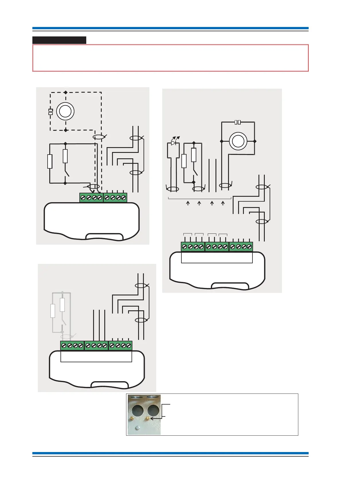
The loop cable screen must be continued through each interface module. The loop, switch input,
zone input and LED output cable screens where used must connect to an earth terminal.
Installation instructions
40
1-Output & 1-input module
connection details
Note 2 - Only channel 1 (terminals 5 & 6) can be
configured as an zone input.
Note 3 - Contact rating 1A 30V ac/dc Resistive load.
Note 4 - Output is 1.5mA @ 24V dc.
Note 1 - When the input is configured as a Zone input
it is possible to attach conventional detectors
and MCPs (with 470 Ohms or 3V9 zener
diode in series with normally open contacts),
maximum load is 2mA @ 24V nominal
(18V minimum) with End-of-line capacitor.
# Can be configured as LED output
The cable screens must be connected to an
on the chassis or in the metal box.
If a module is mounted on a then the
DIN rail must electrically connected to
the
*
earth terminal
DIN rail
loop cable screen via the earth terminal.
EOL 10K
10K
12 11 10 9 8 7 6 5 4 3 2 1
Confirmation
Input
(Not applicable)
NC
COM
NO
Output - Relay
contact rating
1A 30V ac/dc
Resistive load
Loop L1+
Loop 0V
Loop L2+
Loop 0V
#
*
4-Input/Output module
connection details
121110987654321
NO
COM
Relay Outputs
see Note 3
EOL10K
10K
Switch
Input
Zone Input
see Note 2
LED Output
see Note 4
Channel 1
Channel 2
Channel 3
Channel 4
EOL
Loop L1+
Loop 0V
Loop L2+
Loop 0V
*
*
*
*
-Input module
connection details
121110987654321
10K
10K
EOL
Zone Input
Mode
See Note 1
EOL
Capacitor unit
Switch
Input
Mode
Loop L1+
Loop 0V
Loop L2+
Loop 0V
#
*
*
*
Chassis
Z+ Z-
Z+
Z-
87654321