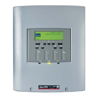
Repeat Indicator panel
The repeat indicator panel provides messages and indications of
system events and connects directly to the fire panel.
Technical data
Dimensions in mm height 177 x width 206 x
depth 48.5
Full assembly weight 750g
Storage temperature 0 to 60ºC
Operating
temperature
0to45ºC
Relative humidity
(Non condensing)
up to 90%
Temperature 5 to 45°C
Ingress protection IP30 estimated
Colour White
Indicators Fire, Fault, Disablement,
Power On, System fault,
Sounder
2 line 20 character per line,
back-lit, display.
Controls
(with flap closed)
Test and Cancel buzzer
Controls
(with flap open)
Fire, Fault, Disablement,
Warning, Display Mode and
Numeric keypad.
"
If only one repeat indicator panel is to be
connected to the fire panel then make use of the 24V
supply at the panel, there is no need to use an external
power supply
¨
Belden No. 9842 EIA RS485 Applications, O/A
Beldfoil® Braid 1Km maximum cable distance
from the
control panel to the last repeat indicator panel
must have
following characteristics:
•
Two twisted pairs
•
24AWG (7 strands x 32 AWG) conductors
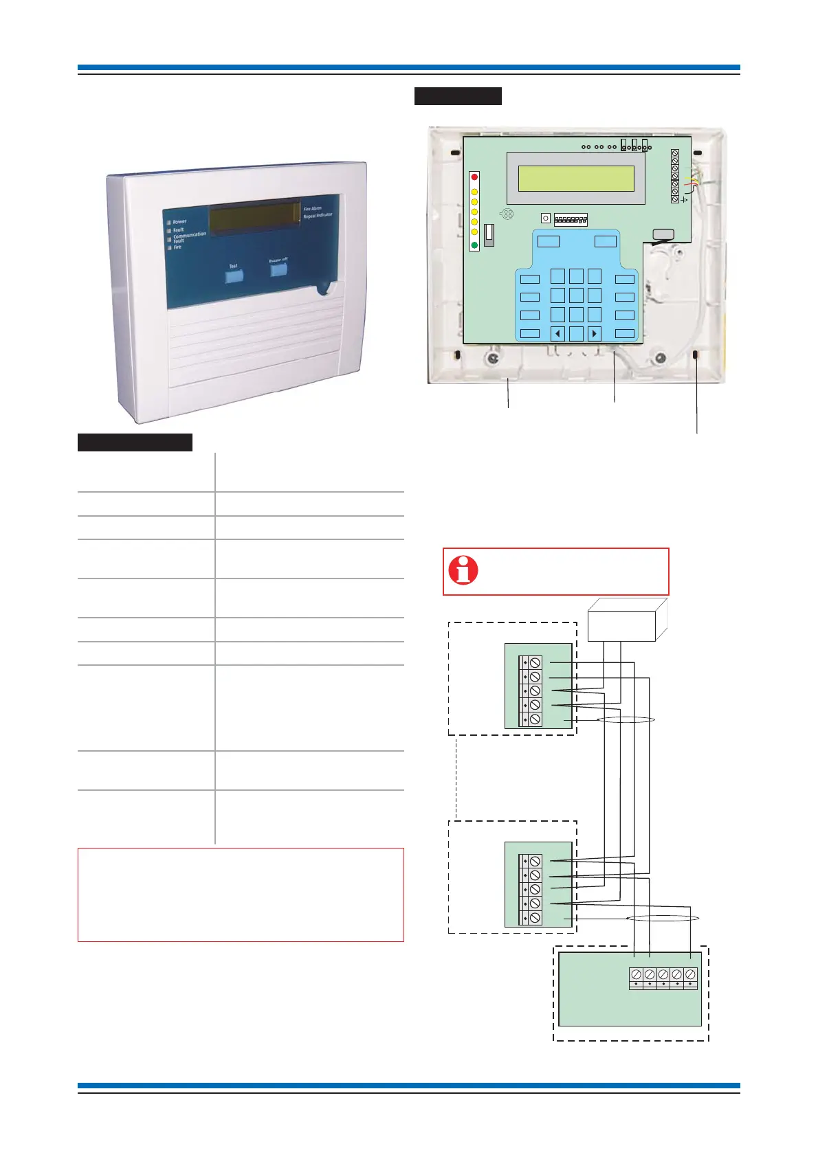
Installation
a. Open the outer cover.
b. Insert the external cable into the backbox assembly at the
required entry point.
c. Mark the fixing points and secure the backbox to the wall.
d. Connect the wires to the respective terminals.
e. Refit the front cover and flap.
Installation instructions
26
123
456
789
0
+
REL
-
24V
a
b
RS485
ON
12345678
J6 J5 J7
Back cable entry point
Thinned sections
on sides of enclosure for
cable entry
4 enclosure fixin
points
PANEL
MAIN CONTROL BOARD
REPEAT INDICATOR PANEL 1
a
b
RS485
earth
REPEAT INDICATOR PANEL 4
-
+
24V
a
b
RS485
earth
UP TO 4 REPEAT INDICATOR
PANELS MAXIMUM
POWER
SUPPLY UNIT
+
-
If there is only one repeat indicator panel
connected then it is possible to use the 24V
supply on the Main control board.
-
+
24V
24V
DRN
RS485
PP3
BA 24V
0V