Installation
Fuse Rating Location
Mains 1.6A HRC - 20x5 mm Top left -back box
FS1 800mA - 20mm x 5mm Board
FS2 800mA - 20mm x 5mm Board
FS3 800mA - 20mm x 5mm Board
FS4 800mA - 20mm x 5mm Board
FS5 2.5A - 20mm x 5mm Board
FS6 250mA - 20mm x 5mm Board
a. Check the package contents, open the door using the key
and check all components.
Component Quantity
Unit 1
Interface Board# 1
Screws (for board)# 7
12V 2.1Ah Battery 2
Key 1
Battery Link 1
Battery lead assembly 1
250mA Aux Fuse (Spare) 1
1.6A Mains Fuse (Spare) 1
2.5A Battery Fuse (Spare) 1
800mA Quick Blow Fuse (Spare) 4
Capacitor Unit (EOL) 4
EOL Label 5
22k Resistor (EOL) 4
# these components are packaged
separately.
b. If necessary, remove the door on the unit to ease
installation and remove the covers fitted over the mains
terminal.
c. Knockout the required cable entry points from the back box.
d. Mark the 3 fixing positions on the wall to which the unit is to
be mounted and secure the unit to the wall with suitable
fixings.
"
If the unit is to switch heavy non-mains loads,
then optional POWER RELAYS 19104-52 must be used.
The relays may be installed on the DIN rail inside the unit.
The relay unit must include a diode unit.
e. Terminate each cable at the entry point.
f. Fit the interface board inside the back box using the
screws provided.
g. Connect the incoming cable ends to the appropriate
terminals.
h. Connect the transformer secondary wires to terminal block
P7 on the interface board.
i. Place the batteries inside the back box, however do not
make the connection, this is done during commissioning
by the Servicing organisation.
j. Fit the cover over the mains terminal and battery
restraint bracket.
k. If removed, re-fit the door and earth lead.
"
The capacitor unit and the 22k Resistor must
be fitted to the end-of-line (EOL) of each circuit. Also
stick an EOL label on the last device in which the EOL
unit is fitted.
l. Close the door on the Unit using the Key.
m. Leave all outstanding parts and installation work to the
Servicing organisation.
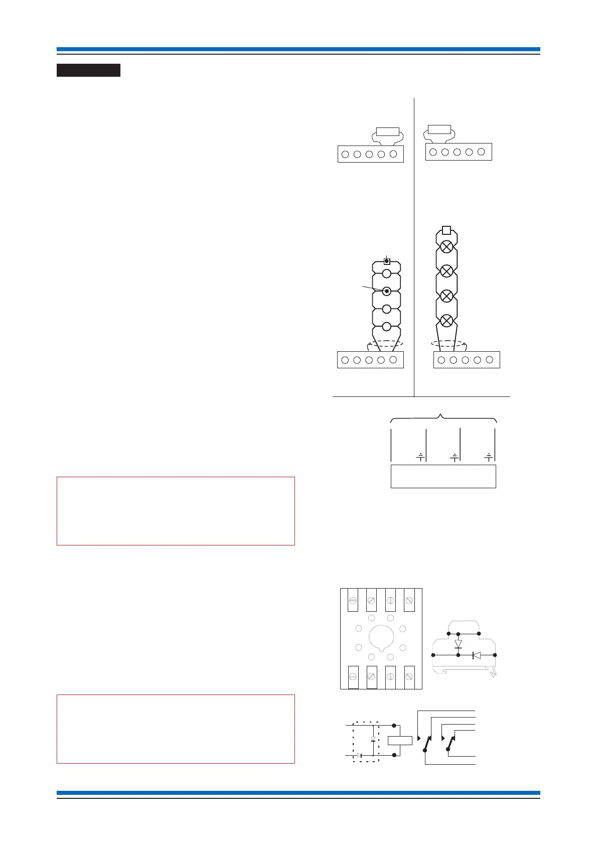
External circuits
Power relay
Up to 4 relays can be fitted inside the interface unit on the DIN
rail.
¨
Octal relay operates from a 24V supply
¨
DIN rail mountable
¨
Relay coil resistance 470R
¨
Contacts rated 10A at 230Vac
45
SenTRI ONE System
S1-
S1+
EARTH
Z1
ZC1
End-of-line
22K Resistor
P3 to P6
OUTPUT USED
S1-
S1+
EARTH
Z1
ZC1
End-of-line
Capacitor unit
P3 to P6
INPUT NOT USED
S1-
S1+
EARTH
Z1
ZC1
P3 to P6
End-of-line
22K Resistor
Conventional
detector or MCP
S1-
S1+
EARTH
Z1
ZC1
P3 to P6
End-of-line
Capacitor unit
INPUT USED
P2
0V LC
0V L1
0V L2
COMMON
LINE
LOOP IN
LINE 1
LOOP OUT
LINE 2
LOOP WIRING
SPUR CIRCUIT
(WHERE USED)
LOOP CIRCUIT
OUTPUT NOT USED
DIODE UNIT
(TS35 DIN RAIL MOUNTABLE)
2S
3S
1S
4S
14 N/O 1
12 N/C 1
24 N/O 2
22 N/C 2
21 COM 2
COIL
A2
-ve
+ve
3S
1S
4S
2S
Diode
Unit
A1
11 COM 1
2
7
3
4
1
6
5
8
6543
24 22 12 14
A2 21 11 A1
7812
HOLDER
TOP VIEW
(TS35 DIN RAIL MOUNTABLE)