Devices per Device loop
"
It is important that redundancy is built into the system to accommodate future expansions.
The number of devices on the loop circuit can be limited by the total number of addresses available, the electrical load on the circuit,
the maximum cable length and other geographical considerations.
¨
The loop circuit must not cover more than 10,000m
2
of floor area of a protected site.
¨
In total a maximum of 127 devices are allowed on the loop circuit.
¨
As a general rule allow 1000 load factor for the loop circuit and only use the 2nd value when calculating the
maximum load factor.
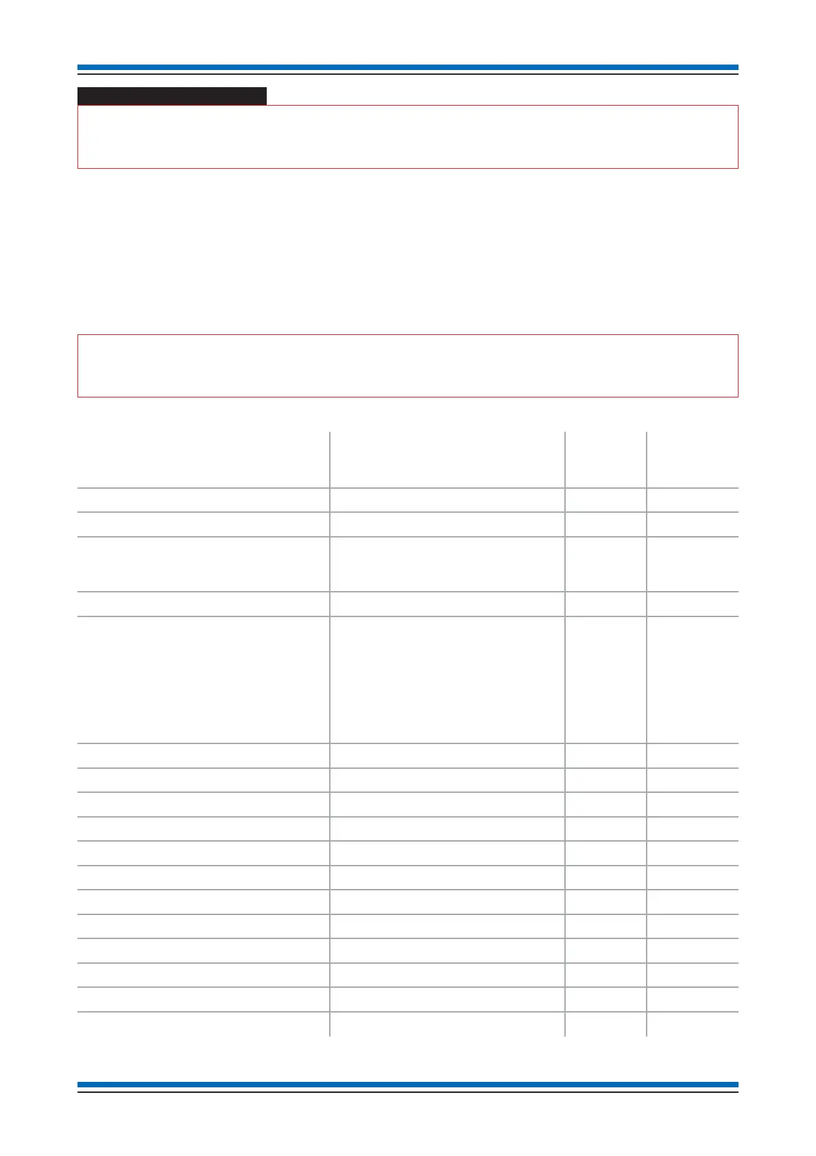
The following table can be used as a rough guide only to determine loop load.
"
For a precise battery standby value use the Battery Standby Calculator. The Battery Standby Calculator
should be used during system design stage using the Commissioning tool.
Device code number Description
Load
factor per
device
Maximum
devices per
loop
SENTRI-RPT Repeat panel (loop powered) 3 4
SENADV-IP-ST-XX (Low profile range) Strobe Red 10 100
SENADV-SN-X (low profile range)
SENADV-IP-SN-X (low profile range)
78400-03NM (system type)
Standard tone 5 127
SENADV-SN-ST-XR (low profile range) Standard tone with red strobe 10 80
SEN-INT-INPUT
SEN-INT-4IO
SEN-INT-OUTPUT
1 - LV Input interface module
4 - LV Input/Output interface module
1 - LV Output Interface module
Switch Input
Relay Output
Zone Input
Every LED Output
1
2
26
5
127
127
32
100
SEN-INT-ACDIN or SEN-INT-AC 1 - MV Output Interface module 5 170
S4-78302-02-NM S4 Mains powered interface 1 8
78301-01NM Mains powered interface 4 8
78321-01NM 4 Channel Loop powered interface 4 30~
SEN-715 Optical Sensor 0.5 200
SEN-720 Heat Sensor 0.5 200
SEN-780 Heat Sensor & Sounder 7 - 13* 127 - 70*
SEN-770-ST Heat Sensor, Sounder & Strobe TBA TBA
SEN-710 Optical Heat Sensor 0.5 200
SEN-770 Optical Heat Sensor & Sounder 6 - 12* 127 - 80*
SEN-DUCT Venturi-Air Duct Kit 0.5 127
SENTRI-BEAM Beam sensor pair 3 per pair 16 (pairs)
Installation instructions
8