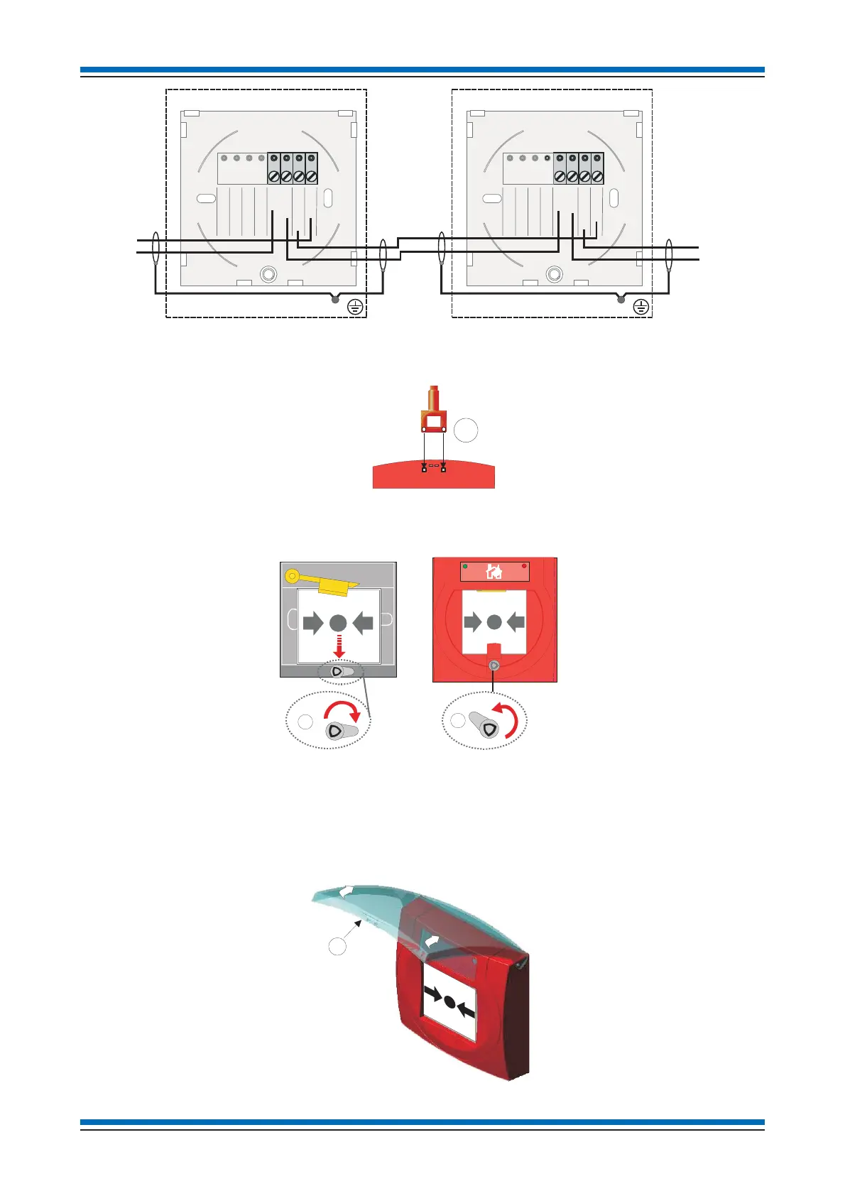
d. Terminate each cable entry at the back box. Use the earth strap or the earth point in the back box to maintain loop cable earth
continuity. Connect the loop cable to the terminals.
e. Disengage front cover from the call point assembly using the end of the test key 'E' and lift out the cover from the bottom edge.
f. Secure the call point assembly to the back box using the 2 long screws supplied.
g. To re-assemble the glass or resettable element, using the test key turn the tab to position 'F' and insert the glass 'A' or optional
resettable element 'B'.
h. Hook the front cover onto the top edge of the call point assembly and then push the bottom edge down until it click shut. Check
both hooks on the top of the front cover are locked onto the call point assembly.
i. Turn the test key anticlockwise to position 'G' (not visible) such that the glass or optional resettable element is held under the
yellow arm.
j. Where applicable, ensure the protective cover 'H' is securely fitted to the call point assembly.
Installation instructions
36
E
F
G
H
1IN
2OUT
4
C
Keyswitch assembly
Loop
In
Loop
In
1IN
2OUT
3
4
C
Keyswitch assembly
Loop
Out
Loop
Out
3