15
SenTRI4 fire system
SENTRI4 panel
SenTRI 4 Fire System
Designed to EN54 Pt 2 & 4
Healthy
15:45
Fault
System Fault
Test
Fire
Power
Power Fault
Disablement
Sounder
1 2 3 4 5 6 7 8 9 10 11 12 13 14 15 16
17 18 19 20 21 22 23 24 25 26 27 28 29 30 30 32
Zones
Previous
Next
Delay
Verify
EN54 Parts 2 & 4
f o u r
0XXXX
042cc
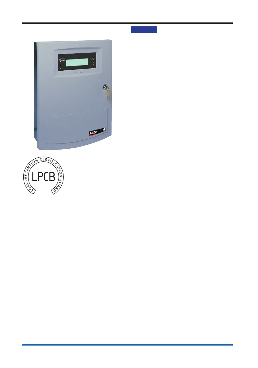
The SENTRI4 panel
(SENTRI4) is an
analogue addressable
re alarm panel
designed to the
requirements of
EN54-2 : 1997 and
EN54-4 : 1997
The panel can
accommodate up to 4 loop circuits for the
connection of Sentri range of analogue
and addressable devices. The panel has
an integral mains derived power supply
and integral batteries. The batteries
supply standby power in the event of
mains power failure. A lockable front door
prevents unauthorised access to re
alarm controls but allows all of the
indicators to be seen. The panel has
integral zonal indicators to provide zone
re or fault indications. Two push button
controls are located on the front door
below the display that enable Fire
messages to be scrolled in the event of
multiple res. The panel is designed for
surface or semi-ush mounting with rear
and top cable entry points.
Features
Analogue addressable re detection
and alarm control
Supports up to four loop circuits per
panel
Up to 200 addressable devices can be
connected to a loop circuit. Devices
like sensors, MCPs and interface units
etc.
Two master alarm circuits
Optional RS485 to connect to a
Repeat Indicator panel
Optional RS232 to connect to another
control panel (domain bridge) or
external printer
USB for commissioning tool
connection
Two sets of auxiliary relay change
over contacts congurable to operate
with re, fault or disablement event
One set of clean voltage-free change
over contacts that operates with re
events
Standby supply to power the system
during mains failure
LCD alphanumeric display with back
light to show event information
Integral 32 zone LED indicators (with
First re steady / ashing or disable
integral zone indication’s options)
LED lights for event indication
Local buzzer gives audible sound to
announce events
Push button for essential controls and
menu options
Four programmable control buttons
(U1 to U4)