21
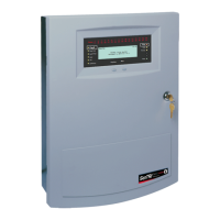
SenTRI4 fire system
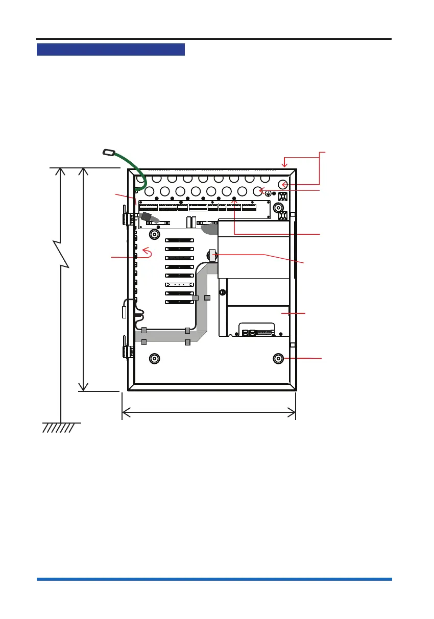
Mounting & cable entry points
These instructions cover installation of the panel and battery box. The cards and
batteries are installed during the commissioning of the system by the servicing
organisation.
The control panel can be surface or ush mounted.
Any unused knockouts that have been removed must not be left open.
502mm
390mm
Cable entry points
18 - Back
21 - Top
3 - Bottom side
(on the right)
Mains supply
cable entry
Knock outs
8-off Earth points
(1-0ff bottom side
on the right hand)
5-off Backbox
fixing points
(includes
1 keyhole)
1.7m
Floor level
Dust
cover
over
backplane
Earth to
inner door
Backplane
0V
to printer
PSU
Adhesive backed
foam pad to seal up
gap to prevent ingress
a. Identify the package SENTRI4 and check that it contains all the parts.
b. Remove the temporary cover from the Back box if used.
c. Knock out/in the required cable entry points from the Control panel back box.
d. Use the xing points provided to mount the Back box to the wall using suitable
xings.