26
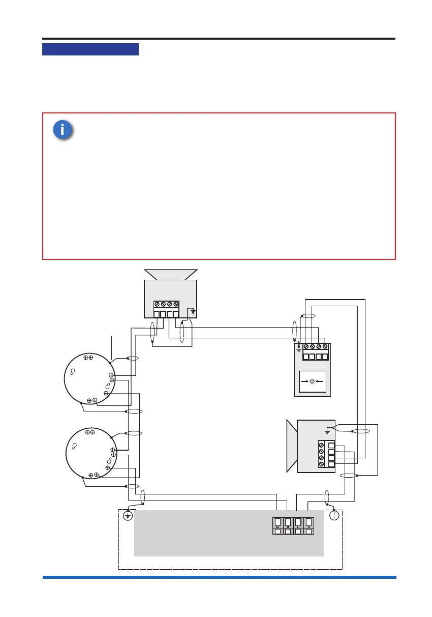
Device loop circuits
Device loop circuits
Upto 4 loop circuits can each accept the connection of compatible addressable devices
/ outstations communicating on 3217 protocol. Where a maximum of up to 200 devices
/ outstations are allowed per loop circuit.
To maintain earth continuity on a loop, the loop cable screen must be continued
through each system device, whether the earth is connected to a device or not.
A loop circuit must not cover more than 10,000m
2
of oor area of a
protected site.
A spur circuit must always be taken from the ‘line common’ terminals
of a 3 ways device.
A spur must not cover more than the equivalent of one zone as
dened in BS 5839 Part 1.
As every loop device has an isolator tted, it is not necessary
to apply special attention where there are more than 32 devices.
However no more than a maximum of 512 devices shall be installed
on one control panel.
L2
02
Sounder Strobe/ VAD device
(2-way)
01
L1
L1
01
L2
02
02
L2
01
L1
L1
0V
Manual call point
L2
0V
PANEL
(2-way)
Earth to
metal box
Master Control Board
LOOP CIRCUIT 1
L1 0V L2 0V
LOOP n
IN4
OUT5
C3
SenTRI device
IN4
OUT5
C3
SenTRI device
Sounder Strobe/ VAD device