29
SenTRI4 fire system
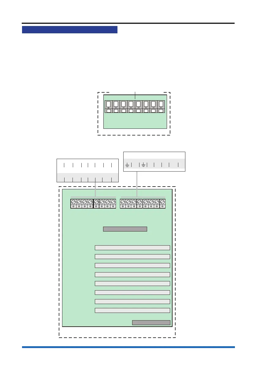
RS232 / RS485 Communication
The control panel offers RS232 and RS485 communication via the IO card.
A standard IO card (not supplied) must be inserted in slot P2 of the backplane of the
panel, which facilitate RS232 and RS485 communication via terminal block P4 on
Terminal card. Note RS232 is PORT 0 and RS485 is PORT 1 with IO card is tted in
slot P2. The domain address and communication baud rate are congured by setting
the DIL switch located on the left edge of the Display Keyboard card.
PANEL
NETWORK CARD IN SLOT P8
0V1 +VE1 -VE1 0V2 N/C +VE2 -VE2 N/C
IO CARD IN SLOT P8
A 5V B 0V CTS Rx RTS TX
Terminal card
PANEL
Backplane
MCC / LCC - P1
LOOP or RS232 - P3
I/O or N/W - P2
LOOP or RS232 - P4
LOOP or RS232 - P5
LOOP or RS232 - P6
LOOP or RS232 - P7
- P8
LOOP, N/W or I/O
IO card
IO or Network
card option
PB1 PB2
IO (RS232) CARD IN SLOT P7
N/C 0V CTS RX RTS TX
IO card option
RS485
A 5V B 0V
RS232
Tx CTS Rx RTS
P4
PORT 1 PORT 0
Terminals for IO card
in slot P2 of the backplane
NOTE: These port settings are
displayed when viewing MCC status.