39
SenTRI4 fire system
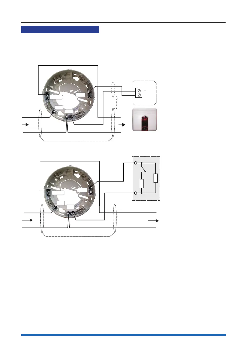
Programmable input/output
All SenTRI Sensor devices can be congured as either monitored input or unmonitored
output. The factory setting of the programmable input / output is set as an unmonitored
output, to drive an external repeat LED without a series resistor. There is a maximum
cable length limit of 15 metres from the SenTRI base to the external I/O Unit.
EM2
OUT5
IN4
C3
L1
0V
L2
+
-
+
ZX18
Remote LED
X1
Monitored LED Output
EM2
OUT5
IN4
C3
L1
0V
L2
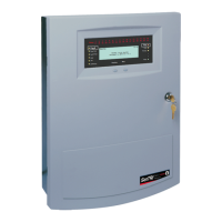
470 Ω
10 KΩ
Input
Beam Transmitter base
The input can accept signals such as re, non re or fault, these are congured during
commissioning. As a re input it is possible to connect a conventional Manual Call
Point (non UK application only) with a series resistor of value 470 Ohms coupled with
an end-of-line 10Kohms resistor. In this case the re input is fully monitored for open or
short circuit faults.
The input can be setup as a non-re or fault input using a similar arrangement with
series and parallel resistors as shown. It is possible for such an input to trigger a
command that is congured to action an output elsewhere in the system to control
plant equipment such as ventilation system in a building.