83
M2 Data Acquisition Device Digital Multimeter Operations
The F2, F3, and F4 fields on the screen are acronyms for the type of test the preset is configured
to perform. Interpret as follows:
• Preset A:
– CGI&S—ground controlled injectors and solenoids
– LF AC—low frequency alternating current signals
– HF AC—high frequency alternating current signals
• Preset B:
– PCI&S—power controlled injectors and solenoids
– LF DS—low frequency digital signals
– HF DS—high frequency digital signals
Values for the available presets are shown in the table below.
Special Selections
The Special settings allow you to alter the way the trace is displayed in order to readily spot signal
anomalies and to compare signals. A short push of the F2, F3, or F4 key activates the indicated
special mode, a long push of the key cancels the special mode.
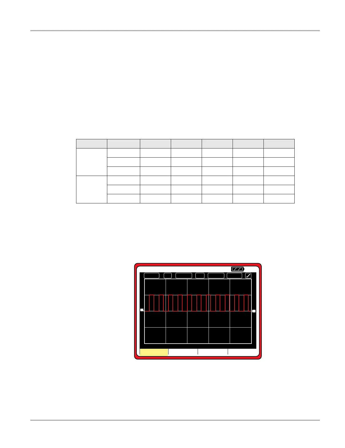
Figure 8-15 Sample special selections screen with peak capture on
Peak
Pressing the F2 key switches on the peak capture function, which allows you to see very fast
signal transitions or glitches. When peak capture is active, “P1” displays at the top of the screen.
Selection Position Timebase Scale Trigger Coupling Slope
Preset A
F2 (CGIS) 10 mS 50 Volts 8 Volts DC Negative
F3 (LF AC) 50 mS 20 Volts 0 Volt AC Positive
F4 (HF AC) 10 mS 20 Volts 0 Volt AC Positive
Preset B
F2 (PCI&S) 10 mS 50 Volts 8 Volt DC Positive
F3 (LF DS) 50 mS 20 Volts 3 Volt DC Positive
F4 (HFDS) 10 mS 20 Volts 3 Volt DC Positive
' ' ' '
&+ '& P6
7$872
7&+
9
9'LY
7
1FBL
4QFDJBM $PVQMJOH*OWFSU
3
 Loading...