Page 3 - 16 SL26/30SL
MANUAL LEVELLING
• There are occasions when the operation of manual levelling is required.
• Manual levelling cannot be carried out above the elevation height (approximately 2 m).
1. Select platform controls from the ground control box. Release the ground “Emergency stop
button” and enter the platform (refer to Figure 2-4).
2. Release the platform “Emergency stop button” (#1) and ensure the machine is switched
OFF with the platform “OFF/ON Engine start switch”(#3).
3. To access the manual levelling mode, press and hold the “Lift/Lower switch” (#12) and the
“Auto level switch” (#14) and switch the machine on using the “OFF/ON Engine start switch”
(#3). Release the toggle switches.
4. When the manual levelling mode is active, the “Lift/Lower enabled LED” (#13) and the “Me-
dium speed drive enabled LED” (#9) will ash.
5. If the platform is out of level from right to left, the “High speed drive enabled LED” (#11) will
ash. If the platform is out of level from front to back, the “Platform tilt-steady red axle tilt”
(#15) will ash.
6. Start the engine.
7. For left to right adjustments, press and hold the “Auto level switch” (#14) then pull in the trig-
ger on the joystick and use the steer switch on the joystick to adjust the platform level to left
or right. The “High speed drive enabled LED” (#11) will extinguish when the platform is level
in that direction.
8. For Fore to Aft adjustment, press and hold the “Auto level switch” (#14) then pull in the trig-
ger on the joystick and push the joystick forward or backwards to adjust the platform level
Fore or Aft. The “Platform tilt-steady red axle tilt” (#15) will extinguish when the platform is
level in that direction.
9. To exit manual levelling mode, switch the machine off.
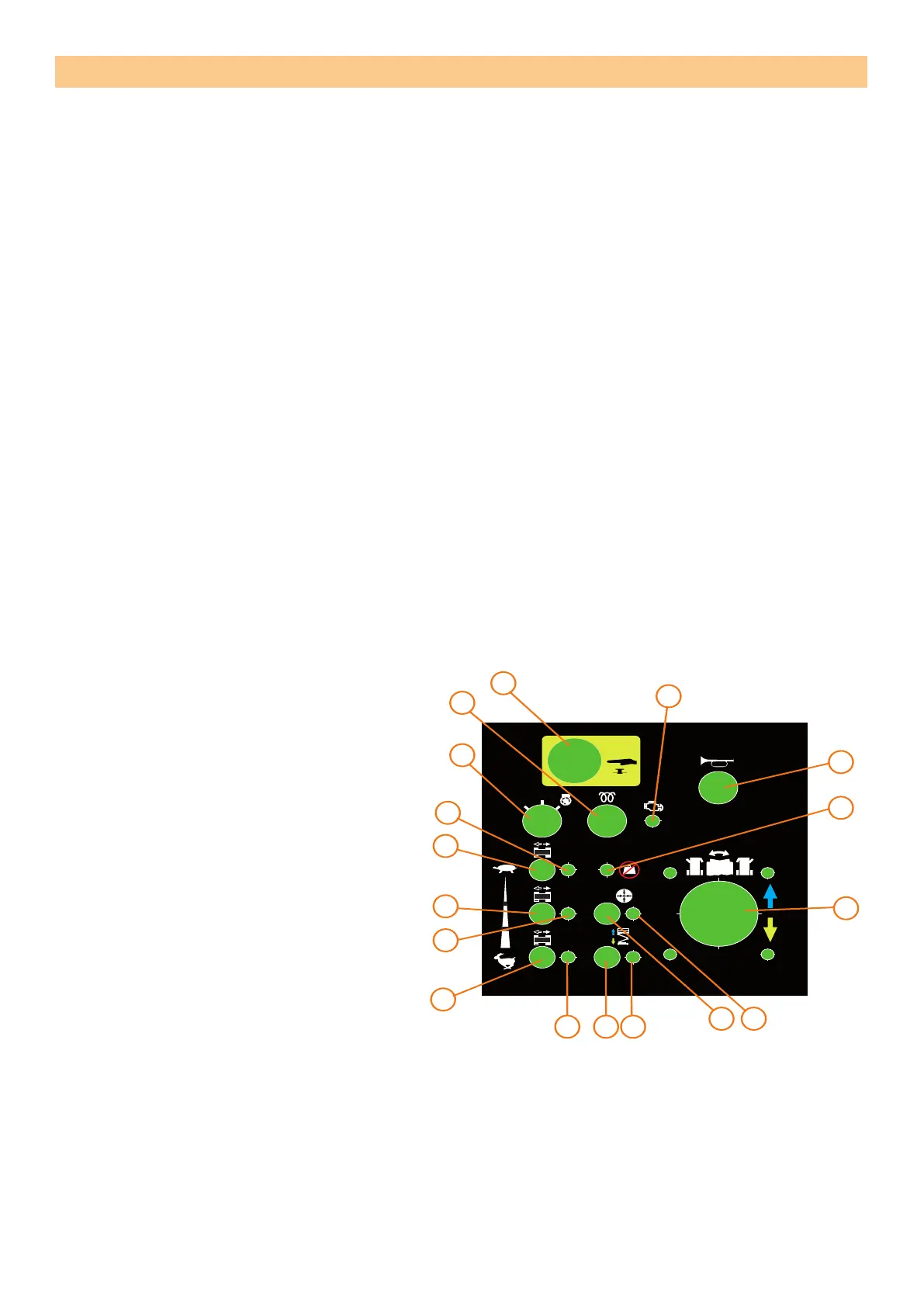
PLATFORM CONTROLS AND
INDICATORS
1. Emergency stop button
2. Horn button
3. OFF/ON Engine start switch
4. Glow plug button
5. Engine warning LED
6. Low speed drive switch
7. Low speed drive enabled LED
8. Medium speed drive switch
9. Medium speed drive enabled LED
10. High speed drive switch
11. High speed drive enabled LED
12. Lift/Lower Switch
13. Lift/Lower enabled LED
14. Auto level switch
15. Platform tilt-steady red
axle tilt - ashing red
16. Overload LED
17. Joystick
SERVICE AND REPAIR
CUTOUT
CUTOUT
CUTOUT
CUTOUT
CUTOUT
CUTOUT
CUTOUT
CUTOUT
CUTOUT
CUTOUT
CUTOUT
CUTOUT
514486-000
0
I
4
1
3
7
6
9
8
10
11 12 13
14 15
17
16
2
5
Figure 3-10: Platform Controls and indicator loca-
tions
 Loading...