43
EN
ATYSp - 542001E - SOCOMEC
7.3.2.3. ATy
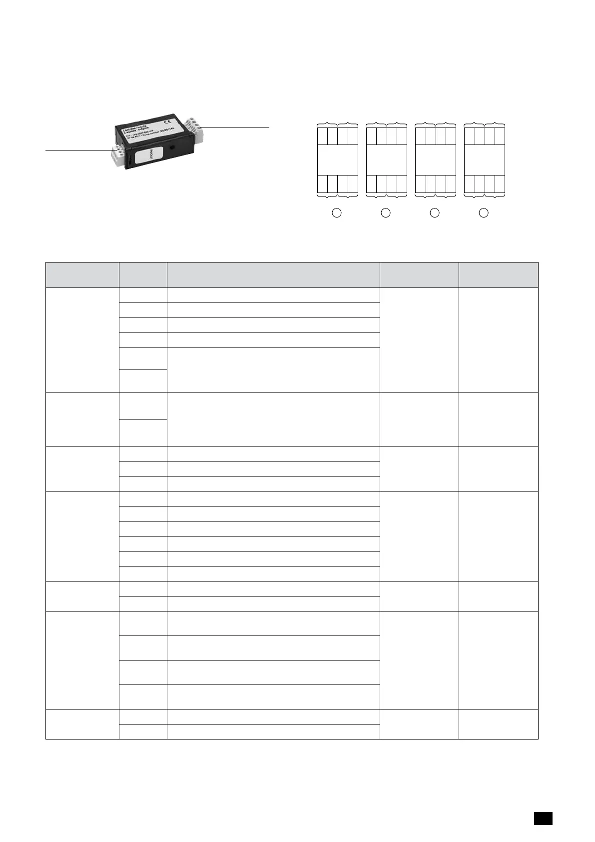
The ATySp can accept a total of 4 plug in I/O modules. (Attn: If using a communication module the total slots
available for extension I/O modules may be reduced to a maximum of 3 with MODBUS RTU and 2 with the Ethernet
module installed).
Outputs
Inputs
I
14
I
13
I
24
I
23
O
24
O
23
O
14
O
13
1
I
14
I
13
I
24
I
23
O
24
O
23
O
14
O
13
2
I
14
I
13
I
24
I
23
O
24
O
23
O
14
O
13
3
I
14
I
13
I
24
I
23
O
24
O
23
O
14
O
13
4
Out9
In13
Out8
In14
Out5
In9
Out4
In10
Out7
In11
Out6
In12
Out3
In7
Out2
In8
7.3.2.4. Terminal denomination, description and characteristics.
Denomination Terminal Description Characteristics Recommended
Cable Section
Output
Contacts
(Motorisation
Module)
04 Aux Contact Position 0 - Normally Open Contact
Dry Contacts
2A AC1 / 250V
2A/24VDC
1.5 – 2.5mm
2
13 Common for Aux Contacts positions I - 0 - II
14 Aux Contact position I: Normally Open Contact
24 Aux Contact position II: Normally Open Contact
63A Motorisation module available output. Closed
when the ATySp is in Auto mode and motorisation
is operational. (No Fault powered and ready to
changeover)
64A
ATS Output
Contact
63B Programmable output dry contacts. (By default
set as POP à ATS control module available output,
closed when the ATySp is in Auto mode and ATS
is operational. (No Fault, powered and ready for a
changeover sequence)
Dry Contacts 2A
AC1 / 250V
1.5 – 2.5mm
2
64B
GensetStart/
StopSignal
71 Signal to Start / Stop the Genset: Common for 72 & 74
Dry Contacts 2A
AC1 / 250V
1.5 – 2.5mm
2
72 Signal to Start / Stop the Genset: NC contact. (71/72)
74 Signal to Start / Stop the Genset: NO contact. (71/74)
AdditionalAux
Contact
Included with
2000A to
3200A
81 Common for Aux Contacts positions I
Dry Contacts 2A
AC1 / 250V
1.5 – 2.5mm
2
82 Aux Contact position I: Normally Closed Contact
84 Aux Contact position I: Normally Open Contact
91 Common for Aux Contacts positions II
92 Aux Contact position II: Normally Closed Contact
94 Aux Contact position II: Normally Open Contact
ATS Power
supply Input I
101 - L/N Power supply I – L/N
208 - 277VAC ± 20%:
50/60Hz
1.5 – 2.5mm
2
102 - N/L Power supply I – N/L
ATSVoltage
SensingInput*
SwitchI
103 - 7/8 Phase or neutral connected on power contact 7 or 8
of Switch I
575 VAC
(ph-ph) max
332Vac
(ph-n) max
1.5 – 2.5mm
2
104 - 5/6 Phase connected on power contact 5 or 6 of Switch
I
105 - 3/4 Phase connected on power contact 3 or 4 of Switch
I
106 - 1/2 Phase or neutral connected on power contact 1 or 2
of Switch I
ATS Power
supply Input II
201 - L/N Power supply II – L/N
208 - 277VAC ± 20%:
50/60Hz
1.5 – 2.5mm
2
202 - N/L Power supply II – N/L

 Loading...


