UPS/NTA GB/DELMP_EXPC1C3C6_B 31
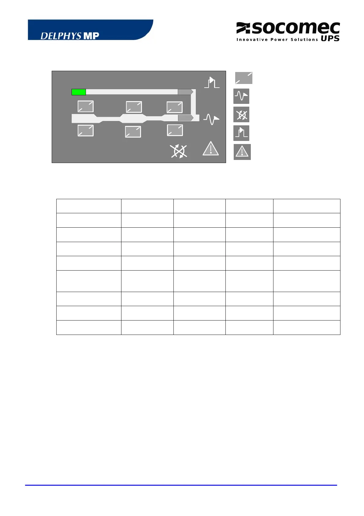
4.4 MIMIC PANEL OF THE CENTRAL BYPASS CABINET
1
modules 1 to 6
General output to the loads
Transfer impossible
Maintenance bypass
2
1
4
5
3
6
3
4
5
7
6
1
2
General alarm
4.4.1 Mimic panel description
SYMBOLS GREEN YELLOW RED BLINKING
MODULES 1 to 6
Connected
Connected and
alarm active
1. BYPASS INPUT
Within tolerances
Without
tolerances
2. LOAD ON
INVERTER
OK Eco-mode active
3. LOAD ON MAINS
If ECO MODE
active
BYP
switch ON
4. OUTPUT TO THE
LOAD
supplied
Load not
supplied
Red: imminent
shutdown of the
system
5. LOAD TRANSFER
impossible
6. MAINTENANCE BYP
ON
Yellow: Maint. byp
alarm
7. GENERAL ALARM
At least one
alarm ON
Yellow: communication
error
4.4.2 Description of the luminous status bar on the central bypass cabinet
Green bar:
- the loads are protected by the inverters
- the loads are supplied via the bypass input if in Eco-mode
- the system operates in the "Energy Saver" mode
(i.e. the number modules ON depends on the energy required)
Yellow bar:
- the loads are supplied via the bypass input
- the loads are supplied via the maintenance bypass
Yellow blinking bar:
- maintenance mode or maintenance alarm active
Red bar:
- the loads are not supplied
Red blinking bar:
- the imminent shutdown alarm is given and the loads will shortly
be disconnected.