UPS/NTA GB/DELMP_EXPC1C3C6_B 33
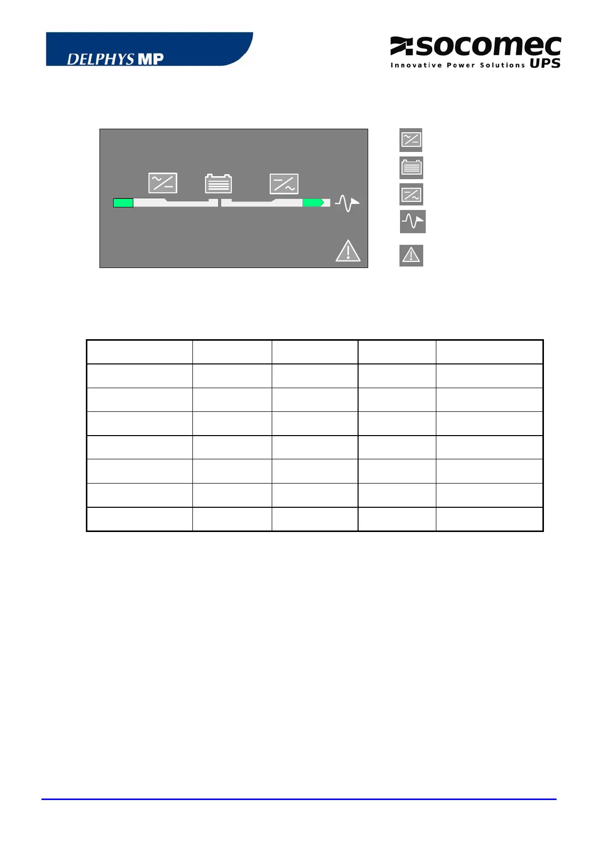
4.5 MIMIC PANEL OF A MODULE
Rectifier and battery
charger
Battery
Inverter
Module output to the
common busbar
1
2
3
4
5
6
7
General alarm
4.5.1 Mimic panel description
SYMBOLS GREEN YELLOW RED BLINKING
1. RECTIFIER INPUT
Within
tolerances
Without
tolerances
2. RECTIFIER
ON Alarm ON
3. BATTERY
Charged discharging
Green: charging
Yellow: battery alarm
4. INVERTER
ON Alarm ON
5. OUTPUT SWITCH
Closed
Closed and
Eco-Mode ON
6. OUTPUT TO THE
COMMON BUSBAR
Module
connected
Module not
connected
Red: imminent stop
7. GENERAL ALARM
General alarm ON
Communication error
4.5.2 Description of the luminous status bar on a module
Green bar:
the module is connected to the common busbar
Yellow bar:
the load is supplied via the automatic or the maintenance
bypass
Yellow blinking bar:
maintenance mode or maintenance alarm active
Red bar:
the load is not supplied
Red blinking bar:
the imminent shutdown alarm is given for the module
OFF
Module isolated