10
MASTERYS BC 60-80 kVA - Ref.: IOMMASBCXX06-EN 06
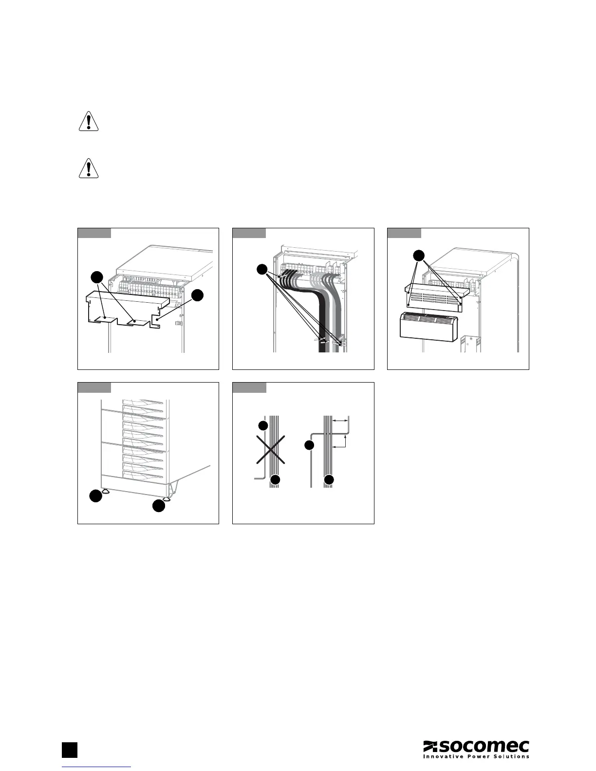
2. UNPACKING AND INSTALLATION OF THE UNIT
2.4-9 Remove the pre-cut element C and curved elements B to feed the cables through.
Secure the cables to the couplings D located on the rack as shown in picture 2.4-10, ensuring the air vents are
not obstructed in any way.
2.4-11 Once cabling has been completed secure the terminal board cover with the four screws A.
Once cabling has been carried out secure the UPS with the fixing feet E as shown in figure 2.4-12.
2.4-13 If the system is installed on a raised floor (such as in a data processing room):
- leave a space of at least 20 cm between the power and the control cables;
- avoid parallel channelling over long distances; choose cables crossing at 90° instead.
2.4-9
2.4-12
2.4-10
2.4-13
2.4-11
E
E
A. power cables
B. control cables
20 cm
90°
A A
B
B
D
A
C
B
2.5. GENERATOR CONNECTION
If your system uses a generator, connect the ‘generator set ready’ no-potential contact to connector IN 2 on the optional ADC
PCB configured in standard or power safe mode (see paragraph 7.2). This automatically extends the voltage and frequency value
range when power is supplied by the generator set.
2.6. EXTERNAL ESD CONNECTION
A remote emergency shutdown system (ESD) can be installed by means of the optional ADC PCB; see paragraph 7.2. Connect
a normally closed zero-potential contact to terminals IN1+ and IN1- of the ADC PCB.
 Loading...