35
ENGLISH
MASTERYS BC 60-80 kVA - Ref.: IOMMASBCXX06-EN 06
ENGLISH
9. ELECTRICAL OPTIONS
9.6. PROTECTION ON MAINS SUPPLY AND ON AUXILIARY MAINS SUPPLY
Activating UPS protection on the mimic panel: access the SERVICE menu on the mimic panel (see the SERVICE menu sec-
tion) and set the SET BACKFEED parameter to 2.BYPASS-INPUT Alone.
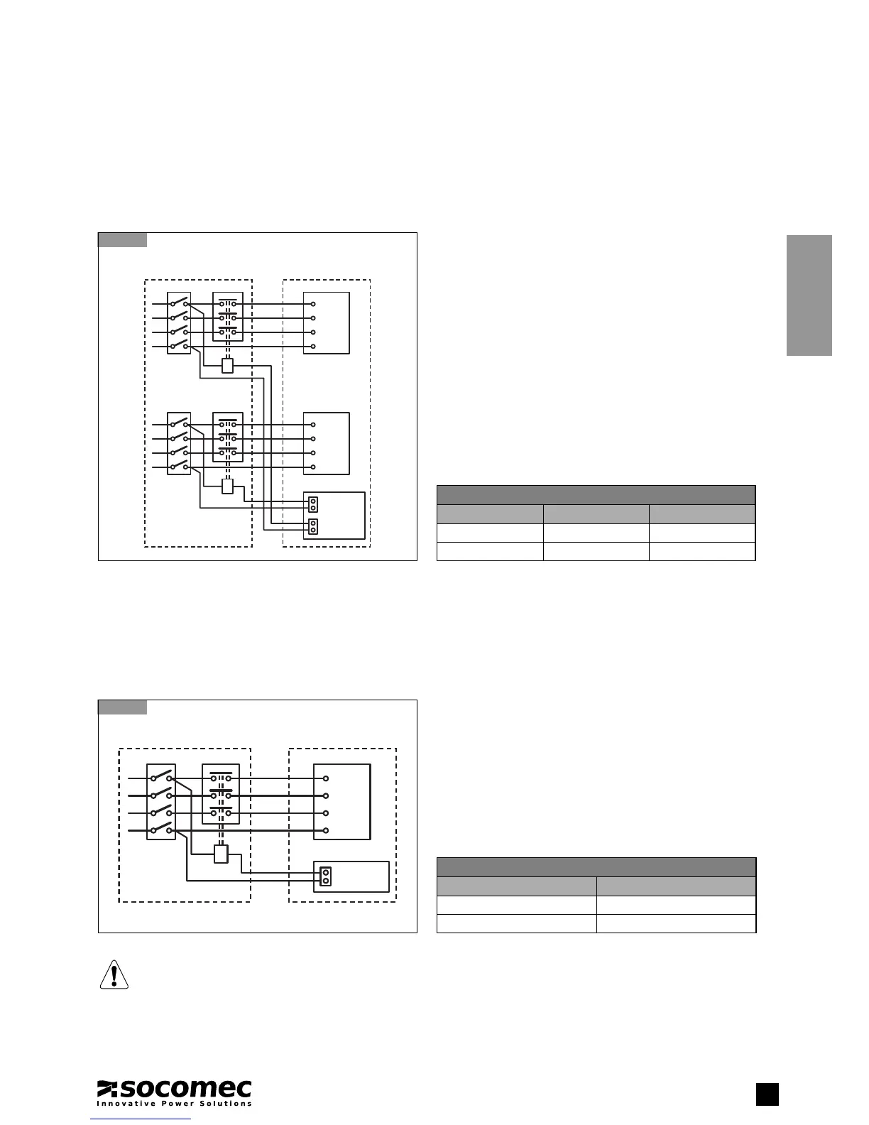
Cable and trunk schematic
9.6-1
UPS 3/3 with separate auxiliary supply
A UPS
L11
Q2
L21
L31
N1
T2
B
M2
L11
L21
L31
N1
XB1
XB2
BKF card
L1
Q1
L2
L3
N
T1
B
M1
L1
L2
L3
N
Key
A Distribution panel
B Remote coil switch
L1-L2-L3-N Input power source
L11-L21-L31-N1 Backup power source
M1 Input power terminal board
M2 Backup power terminal board
T1 Remote switch
1
T2 Remote switch
1
Q1 Input power switch
Q2 Backup power switch
XB1 Connector on BKF PCB
XB2 Connector on BKF PCB
1
Remote switches - rated current
Model T1 T2
60 3/3 125 A AC1 125 A AC1
80 3/3 140 A AC1 140 A AC1
9.7. PROTECTION ON A UPS WITHOUT AUXILIARY MAINS SUPPLY
Activating UPS protection on the mimic panel: access the SERVICE menu on the mimic panel (see the SERVICE menu section) and
set the SET BACKFEED parameter to 3.BYPASS-INPUT Common.
Cable and trunk schematic
9.7-1
UPS 3/3 without separate auxiliary supply
A UPS
L1
Q1
L2
L3
N
T1
B
M1
L1
L2
L3
N
XB1
BKF card
Key
A Distribution panel
B Remote coil switch
L1-L2-L3-N Input power source
M1 Input power terminal board
Q1 Input power switch
T1 Remote switch
1
XB1 Connector on BKF PCB
1
Remote switches - rated current
Model T1
60 3/3 125 A AC1
80 3/3 140 A AC1
WARNING
The neutral connections on the UPS input or output are identical. Consequently there is no risk of high potential
when the input power supply is absent.
However, depending on the type of system connected to the output or in some failure conditions (earth leakage,
significant phase dispersion or in the case of non-insulated neutral systems), high potential can be detected. It
would therefore be necessary to install either adequate neutral switching or a protection system.
 Loading...