20
MASTERYS BC 60-80 kVA - Ref.: IOMMASBCXX06-EN 06
Meaning of LEDs
LED L1 L2 L3 L4 L5 L6 L7
COLOUR GREEN YELLOW GREEN GREEN YELLOW GREEN RED
ON
Rectifi er and
Battery char-
ger on
Operation
from battery-
battery test
Inverter on Auxiliary input
mains present
and Ok
Output on
automatic
bypass mode
Output pow-
ered
Activation
code alarm-
Maintenance
FLASHING
Rectifi er
alarm
Battery sec-
tion alarm
Inverter failure
or fault
Auxiliary input
mains out
of tolerance
General
bypass alarm
Bypass gen-
eral alarm
Inverter failure
or fault
General alarm
OFF
No input
mains present
Battery
charged
Inverter o or
power supply
from auto-
matic bypass
Auxiliary input
mains not
present
Power supply
from inverter
Load not
powered
No alarms
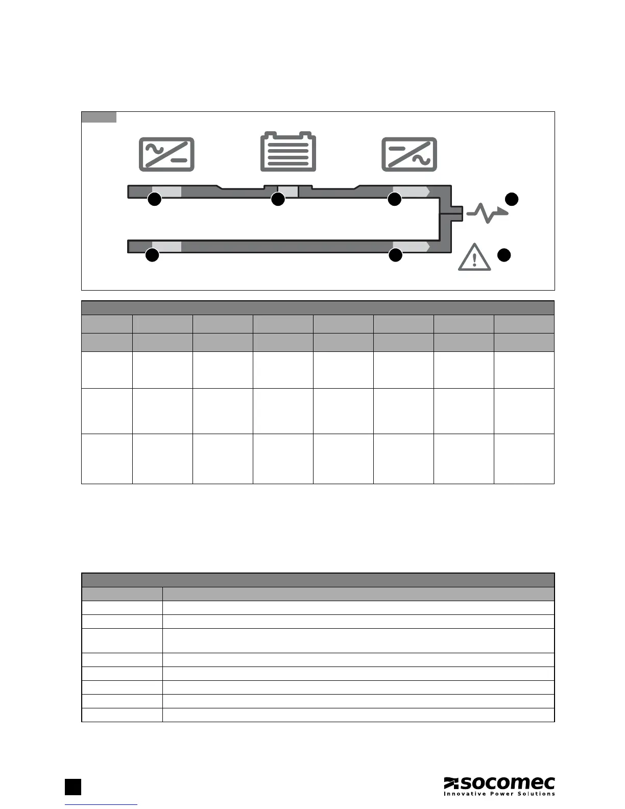
5.1.1. Meaning of LEDs
5.1.1-1
L2L1 L3
L4 L5
L6
L7
5.1.2. Meaning of light bar status
The light bar B (figure 5.1-1) provides immediate indication of the condition of the power supply to the load:
• Red: power supply not present or shutdown imminent.
• Yellow: power supply present but unstable or temporary.
• Green: power supply stable and regular.
5. MIMIC PANEL
Meaning of light bar status
Colour Condition displayed
RED fl ashing Imminent shutdown alarm (the load will be disconnected in a few minutes)
RED Load not powered or battery circuit open
YELLOW fl ashing Alarm requesting standard maintenance after over 25,000-30,000 hours of operation according to
conditions of use (type of load, temperature), (L7 fl ashing and alarm A44) UPS on standby
YELLOW Load on battery or battery discharging if LED 2 is on continuously
YELLOW On automatic bypass if LED 5 is on continuously
YELLOW End of fi rst maintenance period (10,000 hours) UPS in maintenance mode
GREEN fl ashing Battery Test in progress
GREEN Load powered by the inverter or in high e ciency mode
 Loading...