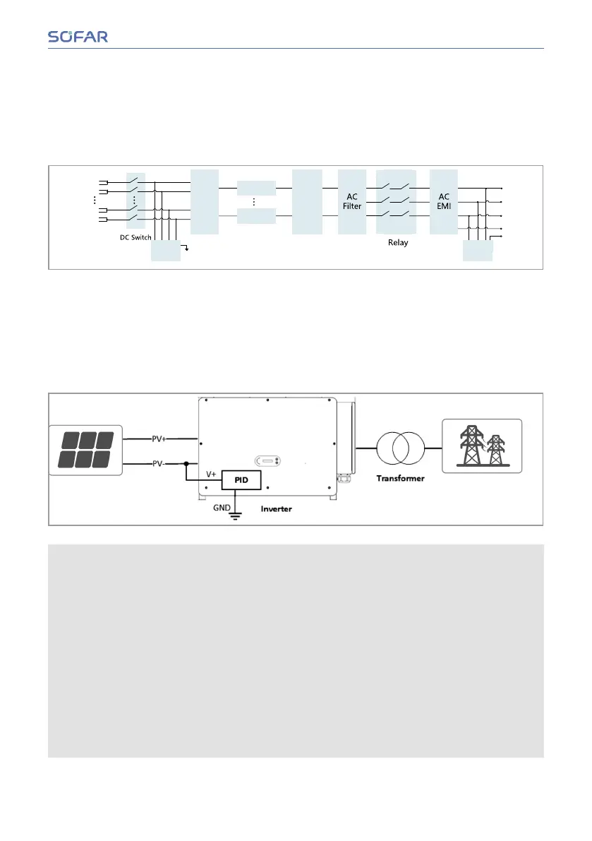
3.6 3.6 Electrical block diagramElectrical block diagram
SOFAR 100...125KTLX-G4 has 20 DC input strings. 10 MPPT tracker’s that converts
direct current of the PV array to grid-compliant, three-phase current and feeds it into the
utility grid. Both DC and AC side has Surge Protection Device (SPD Type II).
PV1+
PE
PV1-
PV10+
PV10-
SPD
Type II
DC/AC
R
S
T
N
PE
SPD
Type II
DC
Filter
MPPT 10
MPPT 1
3.7 3.7 PID RecoveryPID Recovery
When the inverter is running, the PID function module increases the potential between
the negative pole of the photovoltaic array and the ground to a positive value to sup-
pressthePIDeect.
• Before enabling the PID recovery function, ensure that the polarity of the pv
module‘s ground voltage meets requirements. If in doubt, contact the pv module
manufacturer or read their corresponding User Manual.
• If the voltage scheme of the PID protection/recovery function does not meet the re-
quirements of the corresponding PV module, the PID function cannot work properly
or may even damage the PV module.
• Before enabling the reverse PID function, ensure that the inverter has been applied
to the IT system.
• When the inverter is not running, the PID module will apply reverse voltage to the
photovoltaic module to restore the degraded module.
• If the PID recovery function is enabled, the PID works only at night.
• After the PID recovery function is enabled, the PV series voltage to ground is
500Vdc by default. You can change the default value through the App.
Installation and User Manual 17/78
About the Product
 Loading...