17 / 47
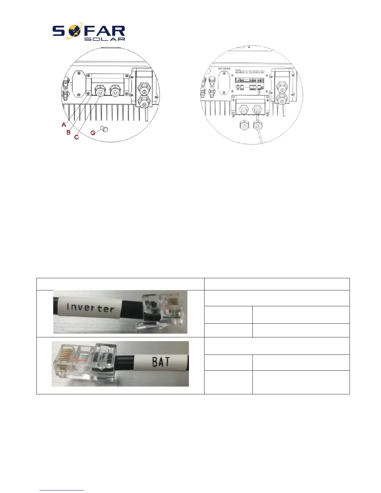
Fig. 12 CT / CAN / RS485 / NTC connection
Step 3: Loosen 4 screws (part A) using a screwdriver (Fig. 12)
Step 4: Remove the waterproof cover (part B), loosen the cable gland (part C), then remove the stopper (part G)
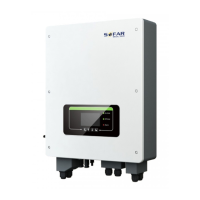
Step 5: Route CT cable through the cable gland, connect CT cable to CT terminal, then insert CT terminal into
corresponding ports.
Step 6: One communication cable (between battery BMS & HYD-ES inverter) is provided in the HYD-ES inverter
accessory bag. One inverter end, one BAT end.
Route the communication cable (inverter end) through the cable gland, insert the 4P4C connector to
HYD3000/4000/5000/6000-ES CAN port. Insert the 8P8C connector (BAT end) to PYLONTECH battery CAN port.