ACM - Access Control Module(s)
44
RM4 Readers
Either Wiegand signaling or Magnetic signaling read heads are connected to
RM-4s or RM-4Es. The RM-4 or RM-4E readers are interfaced through the rear
connector panel. The signals are wired internally to the STAR1 through STAR8
connectors on the ACM. Pin 1 for each connector is shown in the preceding
diagram. It is important that the ports are wired as follows:
The STARn connectors are not keyed so it is possible to reverse the signals. If
the ground connector (pin 4) is connected to +12 VDC (pin 1), damage to the
power supply or the RM could result.
The reader number is determined by a hexadecimal switch on the RM, not by
the Port into which the reader is plugged. To enable the correct reader number,
set the appropriate S2-n hexadecimal switch ON. For example, S2-1 is for
reader 1, S2-2 is for reader 2, etc.
S4 is used to terminate the two wire, half duplex RS485 signals at the iSTAR.
Note that the S4 switch is mounted upside down in the normal front view. This
is done so that switch 1 is on the right and switch 8 is on the left, and the
switches have the same orientation as the ports.
NOTE
The rear connector doors are wired numerically in reverse. Door1 is wired to
STAR8 and Door2 is wired to STAR7, etc. The actual reader number is defined by
the Hex switch in the RM module.
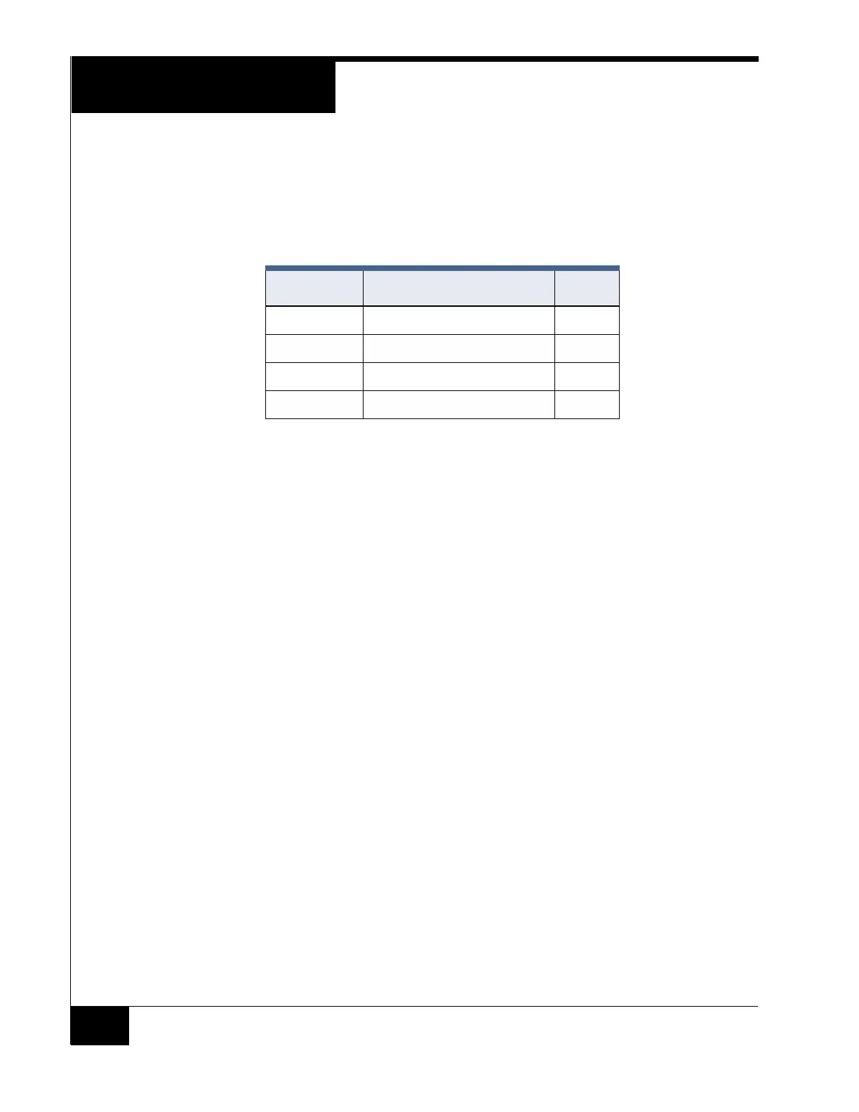
TABLE 17. Pin Signals and Colors
STARx Pin Signal Color
1 +12 VDC Red
2 Tx+ / Rx+ White
3 Tx- / Rx- Green
4 GND Black