Home
Software House
Racks & Stands
iSTAR Pro 4U
Software House iSTAR Pro 4U User Manual
5
of 1
of 1 rating
74 pages
Give review
Manual
Specs
To Next Page
To Next Page
To Previous Page
To Previous Page
Loading...
ACM - Access Control Module(s)
49
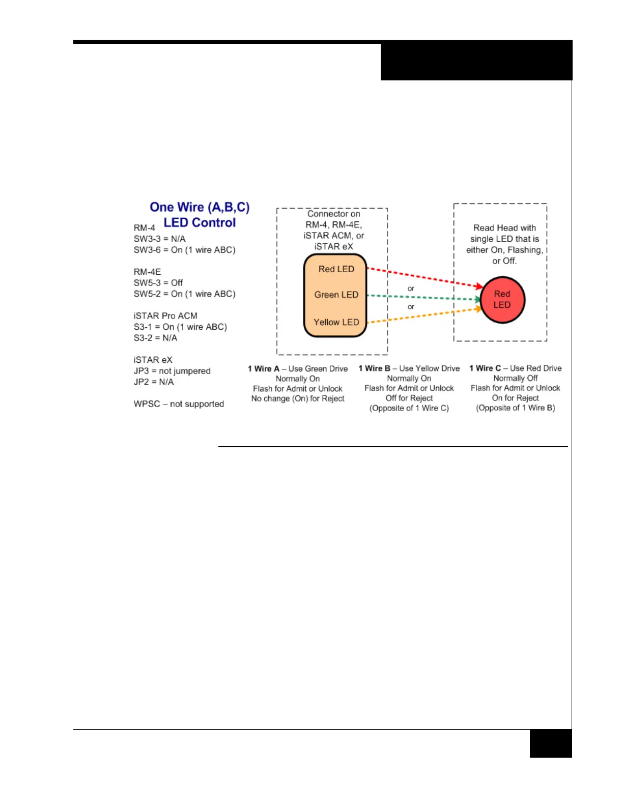
In this case, a single LED drive (Red or Green or Yellow) is wired with varying
results as shown in Figure 31.
Three Wire LED Control mode is typically used for older read heads that have a
single LED that is either On, Off, or flashing.
One Wire (A, B, C)
FIGURE 31. One Wire (A,B,C) LED control
48
50
Table of Contents
System Components
3
Mounting Instructions
5
Network Connection
5
Part Number Description
7
Specifications
8
Indicators and Switches
9
Components/ Connections
12
Rear Connection Panel
14
Power Supplies
20
Battery Backup
21
Power Supply Troubleshooting
22
Cable Distances
32
Input Diagram
34
MAC Address
40
Dip Switches
41
Switch Function
45
Dialup Connection
50
Serial Connection
50
Installation and Wiring
52
Configuration Overview
58
Card Control
61
Sample Events
62
Delay Options
63
Monitoring Station
63
Sample Configurations
66
Maintenance
73
5
Based on 1 rating
Ask a question
Give review
Questions and Answers:
Need help?
Do you have a question about the Software House iSTAR Pro 4U and is the answer not in the manual?
Ask a question
Software House iSTAR Pro 4U Specifications
General
Brand
Software House
Model
iSTAR Pro 4U
Category
Racks & Stands
Language
English