October 21
st
, 2021 22
Integrating Sensors and Accessory Placement
Battery Temperature Sensor
• Place between batteries with tape (See Fig. C).
• This sensor has no polarity and helps perform voltage charging adjustments
and capacity calculations.
Note: Lithium Batteries do NOT require a Temperature sensor.
Limiter Sensors (CT Sensors)
• Install sensors on incoming electrical service wires on L1 and L2 (see Diagrams Section)
• Limited To Home Mode (meter zero) and Peak Shaving Modes require CT sensors
• CT winding default ratio is 2000:1; however, this ratio is programmable
• To ensure the sensors will fit, please check the wire size before ordering
GEN Start Signal (Two-Wire)
• The signal comes from a normally open relay that closes when the Gen Start state is active
CANbus & RS485
• To connect batteries to the Sol-Ark 12K via RJ45, you need to splice the end connecting to the Sol-Ark 12K
• Use the middle two conductors
• RS485 is SunSpec draft 4 (will not work with draft 3)
Wi-Fi Antenna (Dongle)
Remote monitoring and software updates require an internet connection through the Wi-Fi dongle
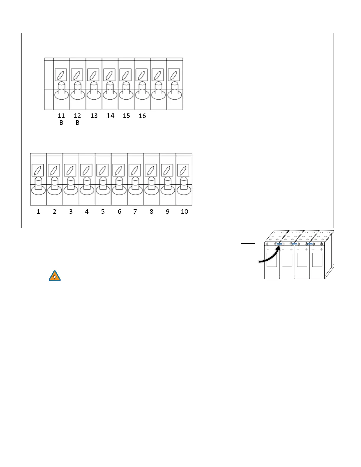
Sensor Pin Out (Located in Sol-Ark user
area)
(1,2) Batt Temp: Battery Temperature Sensor has
no polarity and is needed for voltage correction
when using lead acid batteries.
(+3, -4) CT1 & (+5,-6) CT2: Current transformers
used for limited to home mode and peak shaving
(7,8) Gen Start Relay: Two wire start for
generators, simple open or closed relay
(9,10) Gen On Relay: Not currently used
(B 11, B 12) Emergency Stop: Short these pins to
initiate emergency stop. This will shutdown AC
output from the inverter and initiate rapid
shutdown of the PV.
(+13, -14) Optional 12V input signal for RSD
(+15, -16) 12V power supply for RSD
transmitters: such as TIGO and Midnite
Rated for a maximum of 1.2W (100mA @12V)