October 21
st
, 2021 23
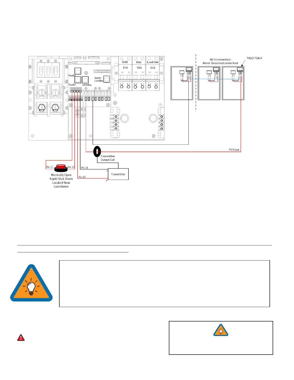
Emergency Stop Signal & PV Rapid Shutdown Signal
Pins 11 and 12 use a normally open switch to connect the two emergency stop pins that cut off the RSD power supply
when triggered, thus stopping the inverter AC output.
Pins 15 and 16 provide the 12V / 100mA signal power lost when the Sol-Ark shuts down using the front button.
Emergency Stop Diagram (Only available on select hardware versions | Shown with TIGO TS4)
Rapid Shutdown: TIGO TS4-A-O | TIGO TS4-A-F | TIGO TS4-O | TIGO TS4-O-DUO | APsmart RSD S-PLC / RSD-D
Disconnect / Transfer Switches: 200A Non-Fused Transfer Switch Model # TC10324R (GE) | 200A Fused
Transfer Switch Model #DG224NRK (Eaton)
PV Fuses: 15A PV MC4 in-line fuse holder (ZOOKOTO or DPJ)
PARALLEL SYSTEMS: Emergency Stop should be connected to the Master with address 01 and will initiate emergency
stop for all paralleled systems from the one button
Powering-Up and Testing the Sol-Ark 12K
Check the voltage on each PV input circuit
A. Should be no higher than 500Voc Temp. corrected
B. DO NOT connect PV+ OR PV- to GND
C. Verify polarity (backward polarity shows 0V)
• The Built-in 12V power supply in the user area of the Sol-Ark (Pins 15 and 16) is rated for
100mA (1.2W)
• Transmitter fits inside the user area of the Sol-Ark 12K but can cause interference
(sometimes requires placing it outside of the user area)
• TIGO Optimizers are compatible with the Sol-Ark 12K (Do not use the built in 12V Power
supply in the Sol-Ark user area to Power the Tigo Optimizer TX transmitter)