August 3, 2019 4
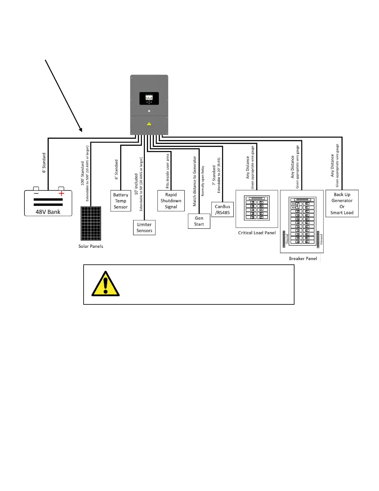
3. Component Distance Guide
WIRE RUN LENGTH: SEE DIAGRAM FOR WIRE GAUGE (AWG) RECOMMENDATIONS, PAGE 11 FOR COMPLETE DETAIL
4. Decide Critical Backup Circuits
a. Decide which 10 circuits will be on backup power continuously. These circuits must use non-
GFI breakers to work with the transfer switch. You can replace a GFI breaker with a normal
breaker, installing GFI outlets instead (or you can move GFI breaker into 10-circuit SW). If
applicable, low load circuits can be combined.
b. Important: Make sure to keep within inverter amperage limits:
On Grid = 50A continuous
Off Grid = 33A continuous/83A peak
c. Verify each load circuit by measuring typical and max Amps with a clip-on Amp meter. Amps x
120V = Watts