Chapter 2: Installing the SolarEdge Firefighter Gateway
Firefighter Gateway Installation Guide MAN-01-00113-1.2
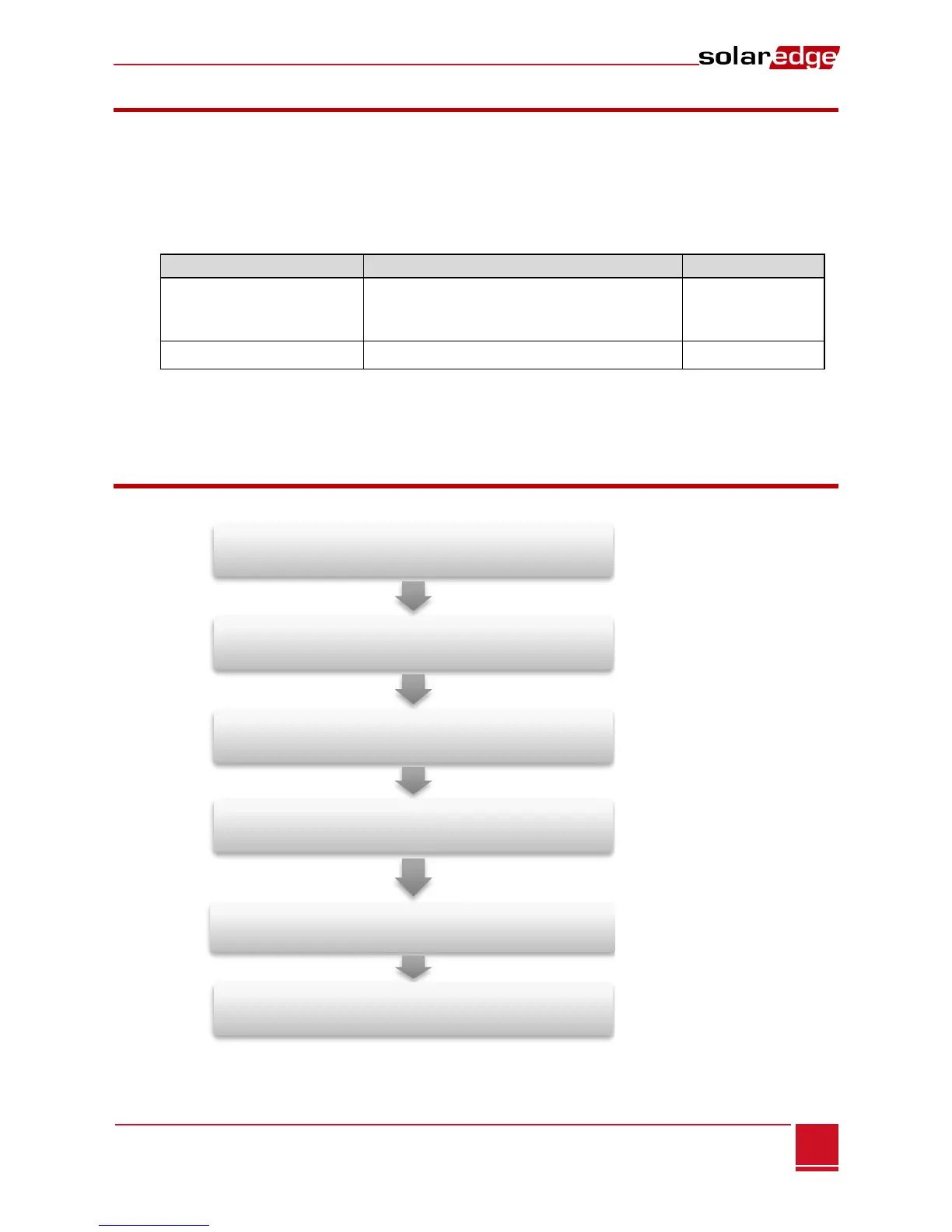
Mounting the firefigher safety gateway
Connecting an emergency stop button or a fire
alarm control system
Connecting the firefighter safety gateway to the
SolarEdge installation
Configuring the
firefighter safey gateway and inverters/SMI
Verifying PV system shutdown using the firefighter
gateway
Using the firefighter safety gateway to connect the
installation to the monitoring server (optional)
Installation Guidelines
The following requirements apply when locating and mounting the SolarEdge Gateway:
The SolarEdge gateway is suitable for mounting indoors. For outdoor installation, use an external
outdoor enclosure (not provided by SolarEdge).
The SolarEdge gateway must always remain in an ambient temperature of -20°C (-4°F) to
+60°C (140°F).
Cable specifications:
RS485 communication bus
(per RS485 port)
Three twisted wires or 4-wire twisted pair
cable (two twisted pairs).
Recommended wire size: 20 AWG / 0.52 mm
2
The SolarEdge gateway power supply requires a socket outlet with a grid voltage of 100 V - 240 V
(50 Hz/60 Hz).
Protect the SolarEdge gateway from dust, wet conditions, corrosive substances and vapors.
Installation Workflow
The following provides an overview of the workflow for installing and setting up the firefighter gateway