Connecting and Configuring an Emergency Stop
Button to the Gateway
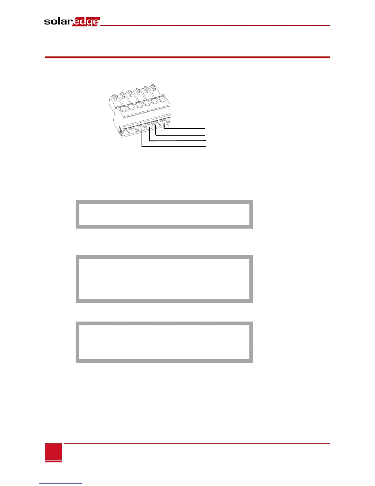
1 Depending on the button/relay type, connect L1/L2, 5V and Ground as described above. Use wire
size 20 AWG/ 0.52mm
2
: Insert the ends of wires into the ports of the supplied 6-pin terminal block.
Figure 9: 6-pin Terminal Block
2 Insert the terminal block into the Control connector on the firefighter gateway.
3 Verify that the SolarEdge gateway is connected to a power outlet.
4 Press the Enter button until the following message is displayed:
P l e a s e ente r
P a s s w o r d
* * * * * * * *
The gateway is now in Setup mode and all its LEDs are lit.
5 Use the three-right-most LCD buttons to type in the following password: 12312312. The following
menu is displayed:
L a n g u a g e < e n g >
C o m m u n i c a t i o n
Rem o t e S h u t d o w n
D i s p l a y
M a i n t e n a n c e
I n f o r m a t i o n
6 Short-press the up/down buttons to scroll to the Remote Shutdown menu. Press the Enter key to
select it. The remote shutdown parameters are displayed:
L 1 P o l a r i t y < N o r m . >
L 2 P o l a r i t y < N o r m . >
S a f e V d c < 1 2 0 V >
C l r A l a r m M o d e < M >
C l e a r A l a r m
7 Set the following:
L1/L2 Polarity: The lines polarity - Normal (default) or Reverse
Normal – safety will be activated when L1/L2 has 5V
Reverse – Safety will be activated when L1/L2 is connected to ground or not connected.
Safe Vdc: Threshold value for safe Vdc: When the maximum DC voltage (of all connected devices)
reaches this threshold, the PV system will be considered safe and the display will show Safe DC in
the main gateway status screen. You may set the threshold in the range between 30 -120V (default
120V)