Wi-Fi Status
This window describes the Wi-Fi configuration:
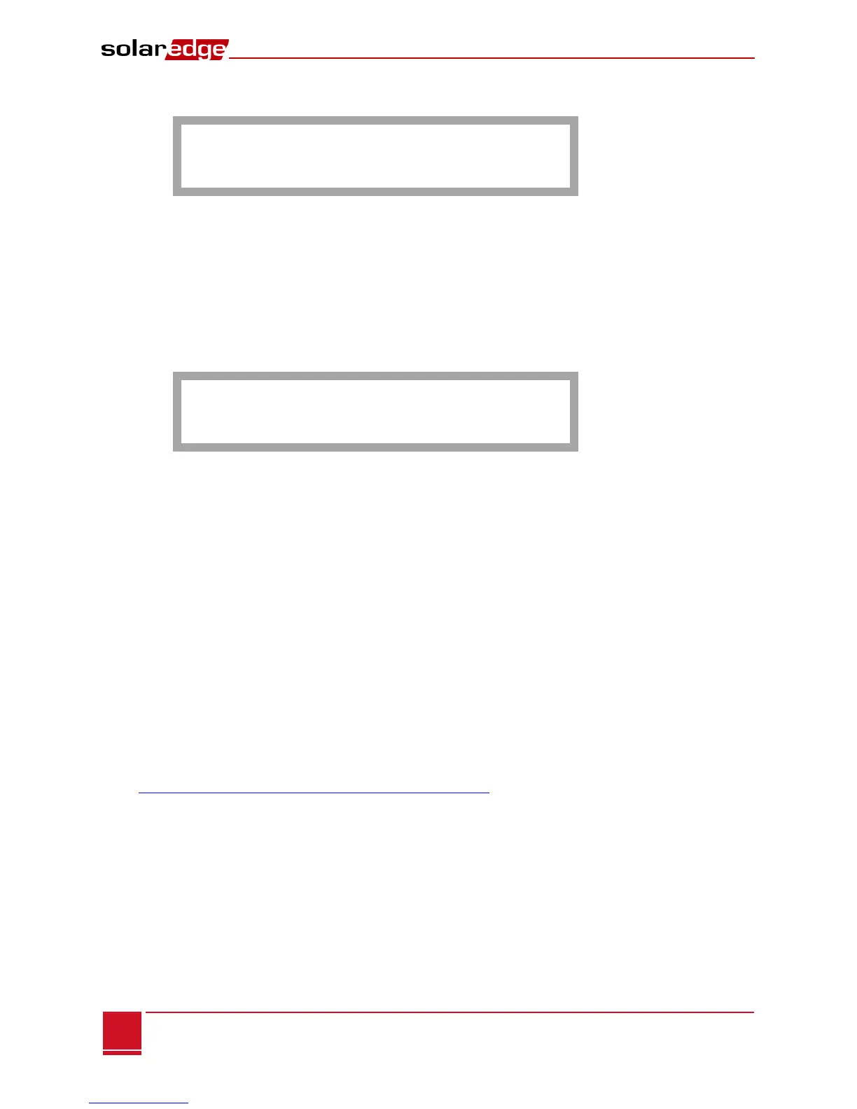
I P : 1 9 2 . 1 6 8 . 2 . 1 1 9
G W : 1 9 2 . 1 6 8 . 2 . 1
S S I D : x x x x x x x x
R S S I : < L / M / H / - >
IP: The DHCP provided address
GW: The gateway IP address
SSID: Service Set Identifier - the name of a wireless local area network (WLAN). All wireless devices
on a WLAN must employ the same SSID in order to communicate with each other.
RSSI: The receive signal strength indication of the closest Wi-Fi in the SolarEdge system. L = low,
M = medium, H = high and (-) = no signal.
Communication Ports Status
D e v P r o t # #
R S 4 8 5 - 1 < S E > < M > < 0 0 >
R S 4 8 5 - 2<- - - ><--><-->
Z i g B e e < S E > < M P S > < -->
This window presents the communication port (RS485-1/2 or ZigBee), and the devices connected to them,
with details about the number, type, and protocol.
DEV: The type of device that was configured to the specific port ( based o the pot’s functionality),
as follows:
SE: SolarEdge device (default)
---: None
PROT: The protocol type to which the port is set:
For a SolarEdge device:
S: SolarEdge slave
M: SolarEdge master
P2P: ZigBee point-to-point
MPM: ZigBee multipoint master (for a ZigBee coordinator module)
MPS: ZigBee multipoint slave (for a ZigBee router module)
For a non-SolarEdge logger:
SS: SunSpec
For non-SolarEdge inverter readers and electricity meters, refer to
http://www.solaredge.com/articles/se-supported-devices.
##: The total number of slaves detected on the specific port