Creating an Ethernet (LAN) Connection
Overview
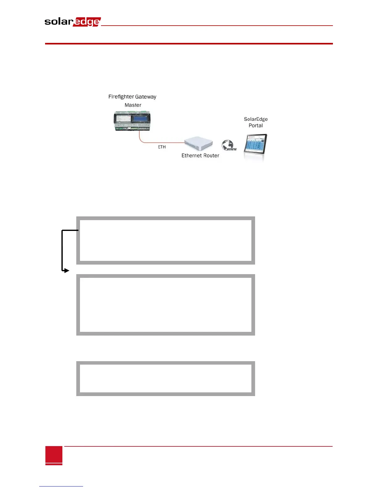
This communication option enables using an Ethernet connection to connect the SolarEdge gateway to the
SolarEdge monitoring portal through a LAN. The SolarEdge gateway has an RJ45 connector for Ethernet
communication.
Figure 17: Example of Ethernet Connection
Ethernet Communication Configuration Options
The following is a description of the options to configure the Ethernet (LAN) port settings.
Communication:
S e r v e r < L A N >
L A N C o n f
R S 4 8 5 – 1 C o n f < S >
R S 4 8 5 – 2 C o n f < >
Z i g B e e C o n f < >
R S 2 3 2 C o n f
LAN Conf
I P C o n f i g
S e t D H C P < e n >
S e t I P
S e t M a s k
S e t G a t e w a y
S e t D N S
S e t S e r v e r A d d r
S e t S e r v e r P o r t
IP Config: Displays the current IP configuration of the gateway, as shown below. If DHCP is used, this
screen reflects the parameters retrieved from the DHCP server. If manual settings are used, the
screen shows the last manually input configurations.
I P 0 . 0 . 0 . 0
MSK 2 5 5 . 2 5 5 . 2 5 5 . 0
G W 1 9 2 . 1 6 8 . 0 . 1
D N S 0 . 0 . 0 . 0
Set DHCP <En>: If the LAN connection between the gateway and the SolarEdge Monitoring Portal has
a DHCP server, enable this option by setting it to Enable (default). If this option is enabled, then the
DHCP server automatically configures the IP, Subnet Mask, gateway and DNS. If not, set them
manually.