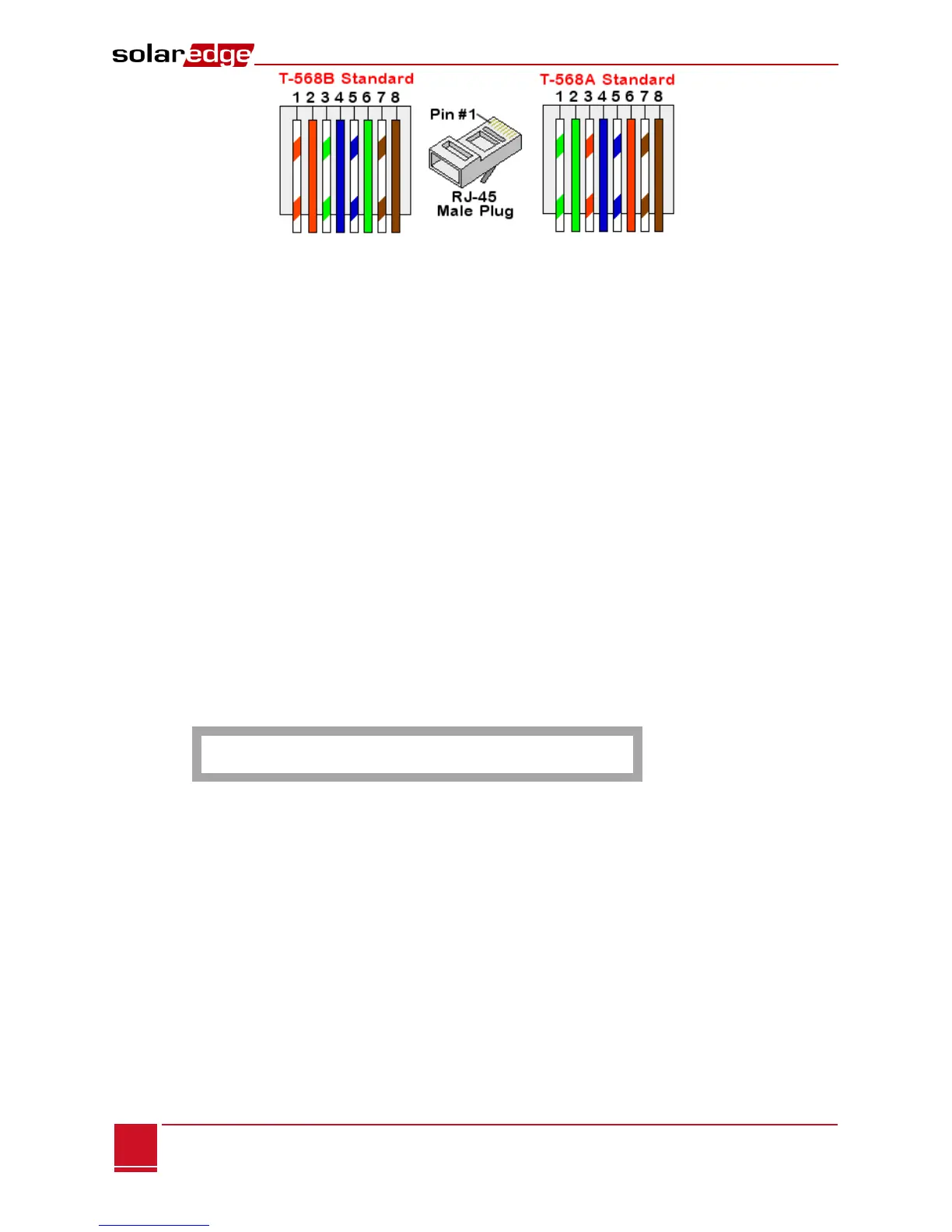
Figure 18: Standard cable wiring
1 Connect one end of the Ethernet cable to the RJ45 plug at the router or Ethernet gateway that
is connected to the Internet.
2 Connect the other end to the SolarEdge gateway Ethernet connector.
3 Verify that the yellow communication LED turns ON.
► To configure Ethernet communication to the SolarEdge monitoring portal:
The device connected to the monitoring portal has to be defined as the master device.
The server communication method is configured by default to LAN with DHCP enabled. If a different
setting is required, follow the steps below:
1 Enter Setup mode, as described in Setup Menu Options on page 29.
4 Set the gateway as the master of the RS485 bus and perform slave detection as described in To
configure the RS485 communication bus with SolarEdge inverters/SMI: on page 21.
2 To configure the LAN to Static IP select the following in the LCD menus on the gateway:
Communication Server LAN
LAN Conf Set DHCP <Dis>
5 Set the IP, mask, gateway DNS, server address, and server port as necessary using the LCD User
buttons. Refer to the Ethernet Communication Configuration Options on page 36.
3 Verify the that the status field in the Server Communication Status window displays S_OK:
S e r v e r : L A N < S _ O K >
S t a t u s : < O K >
4 Exit the Setup mode.