If connecting more modules than optimizer inputs in parallel, use a branch cable.
Some commercial power optimizer models have a dual input.
Position the power optimizer close enough to its module so that their cables can be
connected.
Make sure to use power optimizers that have the required output conductor length:
Do not
use extension cables between a module and a power optimizer,
between two modules connected to the same optimizer, or between two
optimizers other than in the cases specified below.
You can use extension cables between power optimizers only from row to row,
around obstacles or pathways within a row, and from the end of the string to
the inverter, as long as the maximum distance is not exceeded.
NOTE
Use at least 11 AWG/ 4 mm² DC cables.
The total cable length of the string (excluding power optimizers’
cables) should not exceed 1000ft./300 m from DC+ to DC- of the
inverter.
Completely shaded modules may cause their power optimizers to temporarily shut
down. This will not affect the performance of the other power optimizers in the
string, as long as the minimum number of unshaded power optimizers connected in
a string of modules is met. If under typical conditions fewer than the minimum
optimizers are connected to unshaded modules, add more optimizers to the string.
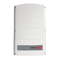
To allow for heat dissipation, maintain a minimum of 2.5 cm / 1" clearance between
the power optimizer and other surfaces, on all sides except the mounting bracket
side.
Figure 2: Power optimizer clearance
Chapter 2: Installing the Power Optimizers 15
Single Phase Inverter with HD-Wave Technology Installation MAN-01-00540-1.0