1. Remove the inverter cover as described in
Removing the Inverter Cover
on
page 50.
2. Remove the seal from one of the openings in communication gland and insert the
wire through the opening.
3.
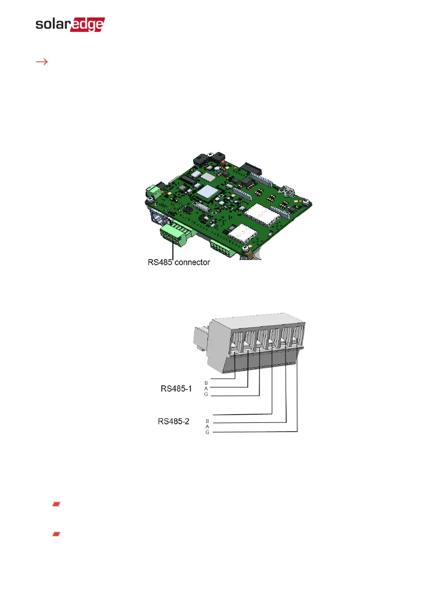
Pull out the RS485 terminal block connector, as shown below:
Figure 22: The RS485 terminal block
4.
Loosen the screws of pins A(+), B(-), and G on the left of the RS485 terminal block
(RS485-1 ).
Figure 23: RS485 terminal block
5.
Insert the wire ends into the G, A and B pins shown above. Use Four- or six-wire
twisted pair cable for this connection.
You can use any color wire for each of the A, B and G connections, as long as:
The same color wire is used for all A pins the same color for all B pins and the
same color for all G pins
The wire for G is not from the same twisted pair as A or B.
6.
For creating an RS485 bus - connect all B, A and G pins in all inverters. The following
figure shows this connection schema:
Chapter 6: Setting Up Communication to the Monitoring Platform 55
Single Phase Inverter with HD-Wave Technology Installation MAN-01-00540-1.0
To connect the RS485 communication bus:w