Figure 22: Rubber fitting
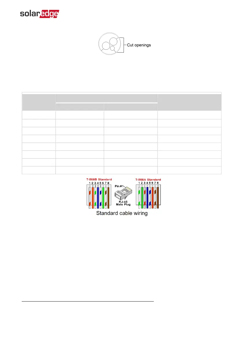
CAT5/6 standard cables have eight wires (four twisted pairs), as shown in the diagram
below. Wire colors may differ from one cable to another. You can use either wiring
standard, as long as both sides of the cable have the same pin-out and color-coding.
RJ45 Pin #
Wire Color
(1)
10Base-T Signal
100Base-TX Signal
T568B T568A
1 White/Orange White/Green Transmit+
2 Orange Green Transmit-
3 White/Green White/Orange Receive+
4 Blue Blue Reserved
5 White/Blue White/Blue Reserved
6 Green Orange Received-
7 White/Brown White/Brown Reserved
8 Brown Brown Reserved
Figure 23: Standard cable wiring
6. Use a pre-crimped cable to connect via gland #1 to the RJ45 plug on the inverter's
communication board or, if using a spool of cable, connect as follows:
a. Insert the cable through gland #1.
b. Remove the cable’s external insulation using a crimping tool or cable cutter and
expose eight wires.
c. Insert the eight wires into an RJ45 connector, as described in
Figure 23
.
(1)
The inverter connection does not support RX/TX polarity change. Supporting crossover Ethernet cables
depends on the switch capabilities.
Chapter 7: Setting Up Communication to the Monitoring Platform 71
Three Phase System MAN-01-00507-4.2