Figure 22: Standard cable wiring
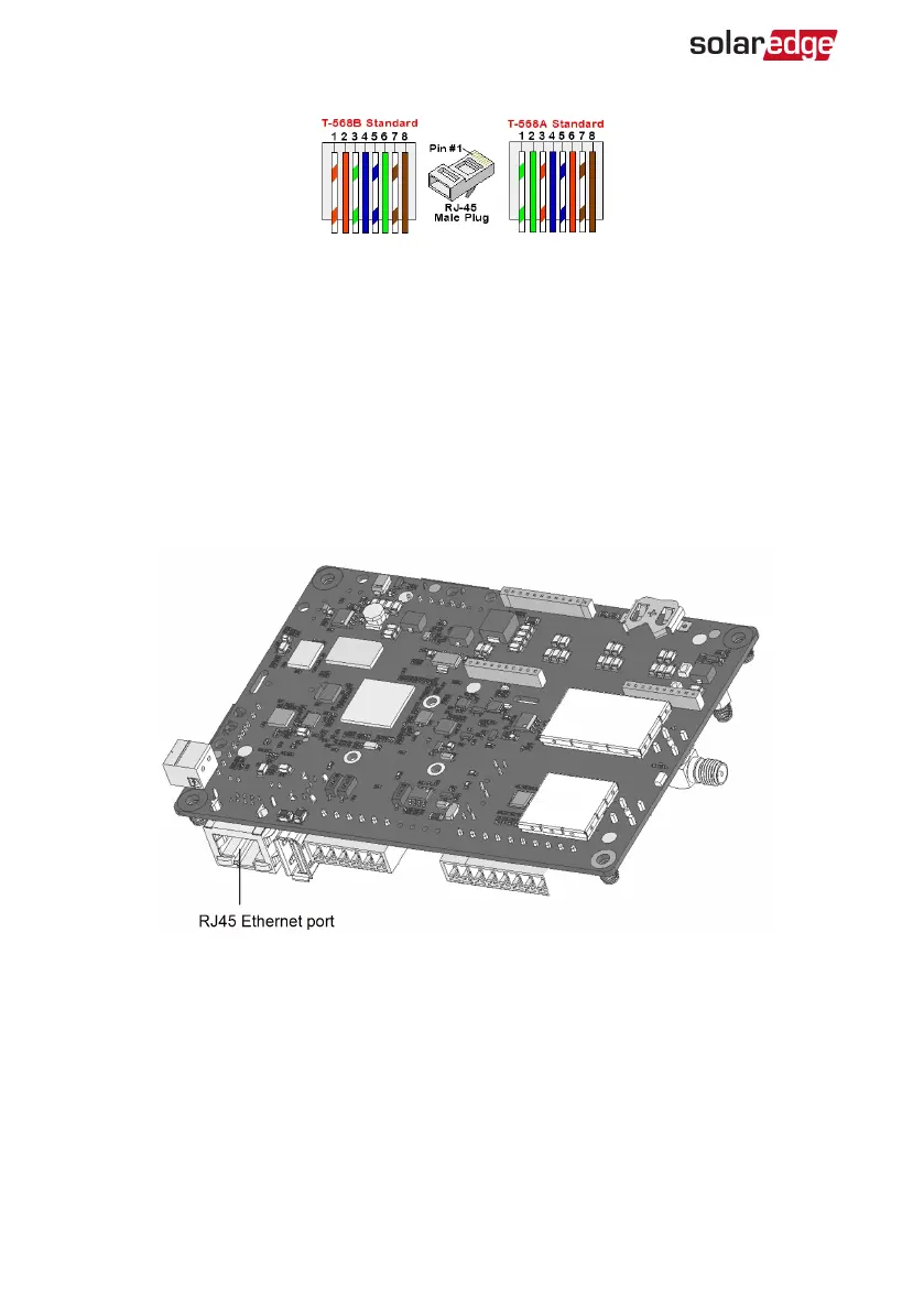
6. Use a pre-crimped cable to connect via gland #1 to the RJ45 plug on the inverter's
communication board or, if using a spool of cable, connect as follows:
a. Insert the cable through the gland.
b. Remove the cable’s external insulation using a crimping tool or cable cutter and
expose eight wires.
c. Insert the eight wires into an RJ45 connector, as described in
Figure 22
d. Use a crimping tool to crimp the connector.
e. Connect the Ethernet connector to the RJ45 port on the communication board.
Figure 23: The RJ45 Ethernet connection
7. For the switch/router side, use a pre-crimped cable or use a crimper to prepare an
RJ45 communication connector: Insert the eight wires into the RJ45 connector in the
same order as above (
Figure 22
).
8. Connect the cable RJ45 connector to the RJ45 port of the Ethernet switch or router.
You can connect more than one inverter to the same switch/router or to different
switches/routers, as needed. Each inverter sends its monitored data independently
to the SolarEdge monitoring platform.
EV Charging Single Phase Inverter MAN-01-00629-1.2
59 Creating an Ethernet (LAN) Connection