21
4 Preparation before Installation
4.4.3 Accessory
BMS (
TBMS-MCS0800
)
A
D
G
C
E*
F*
H
I J
B
K L M N
O
P
S
Q
R
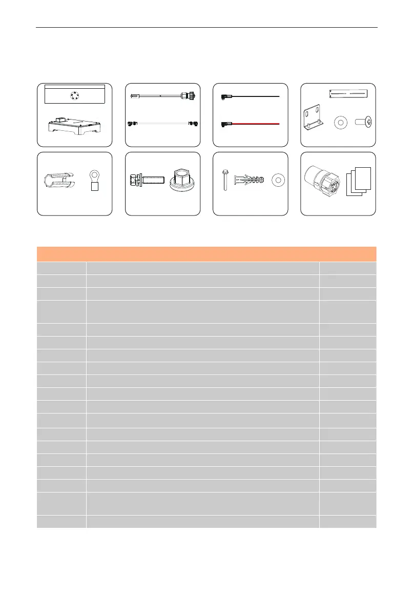
Accessories included are shown as follows:
Item No. Description Quantity
A BMS 1
B Base 1
C Communication Cable (BMS port) 1
D
Short Power Cable (is plugged into the jack of BMS before
delivery)
1
E* Power Cable (Black) 1
F* Power Cable (Red) 1
G “L” Bracket 1
H Adjustable Bracket 1
I M4 Washer 2
J M4x14 Phillips-head Screw 2
K Rotation Wrench 1
L RNB4-5 Current Terminal 2
M M4x15 Phillips-head Screw 2
N M6 Flange Nut 2
O Tapping Screw 2
P Expansion Bolt 2
Q Washer 2
R
Short-circuit Plug (It will be installed on the HEAT port before
delivery)
1
S Document 1
*Note: The mark “*“ indicates that the connector connecting inverter on the
power cables, connecting BMS and inverter, is delivered with the inverter’s
accessories kit.
 Loading...