32
6 Wiring
6.2 Communication Connection (connecting to inverter)
To ensure normal operation of BMS and inverter, the BMS communication cable
delivered with the BMS accessories kit is required to connect RJ45 connector.
The specific definition of the communication cable is shown as follows:
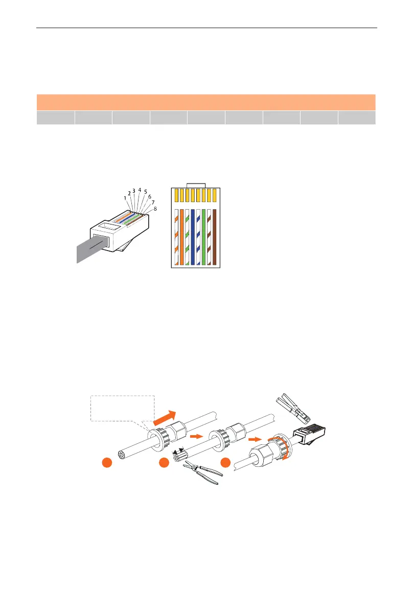
PIN 1 2 3 4 5 6 7 8
BMS / GND / BMS_H BMS_L / A1 B1
The wire sequence of one terminal connecting to the inverter is the same as the
wire sequence of the other terminal, connecting to the BMS.
The wire sequence is shown as follows:
1 2
3
4
5
6 7 8
1) White with orange stripes
2) Orange
3) White with green stripes
4) Blue
5) White with blue strips
6) Green
7) White with brown stripes
8) Brown
The steps for making RJ45 connector to BMS communication cable are shown
as follows:
Step 1: Strip the cable jacket about 15 mm down from the end;
Step 2: Carefully insert the wires all the way into the RJ45 connector, making
sure that each wire passes through the appropriate guides inside the connector;
Step 3: Push the RJ45 inside the crimping tool and squeeze the crimper all the
way down.
Rotate
anti-clockwise
to loosen
1 2 3
*Note: The BMS communication cable shall have a shield layer.
 Loading...