6.1 Grid Connection
X1-Retro Fit series inverter are designed for single phase grid. Voltage is
220/230/240V, frequency is 50/60Hz. Other technical requests should comply
with the requirement of the local public grid.
Micro-breaker should be installed between inverter and grid, any load should
not be connected with inverter directly.
Table 4 Cable and Micro-breaker recommended
Connection Steps:
Step1. Check the grid voltage.
1.1 Check the grid voltage and compare with the permissive voltage range (Please refer to
technical data).
1.2 Disconnect the circuit-bricker from all the phases and secure against re-connection.
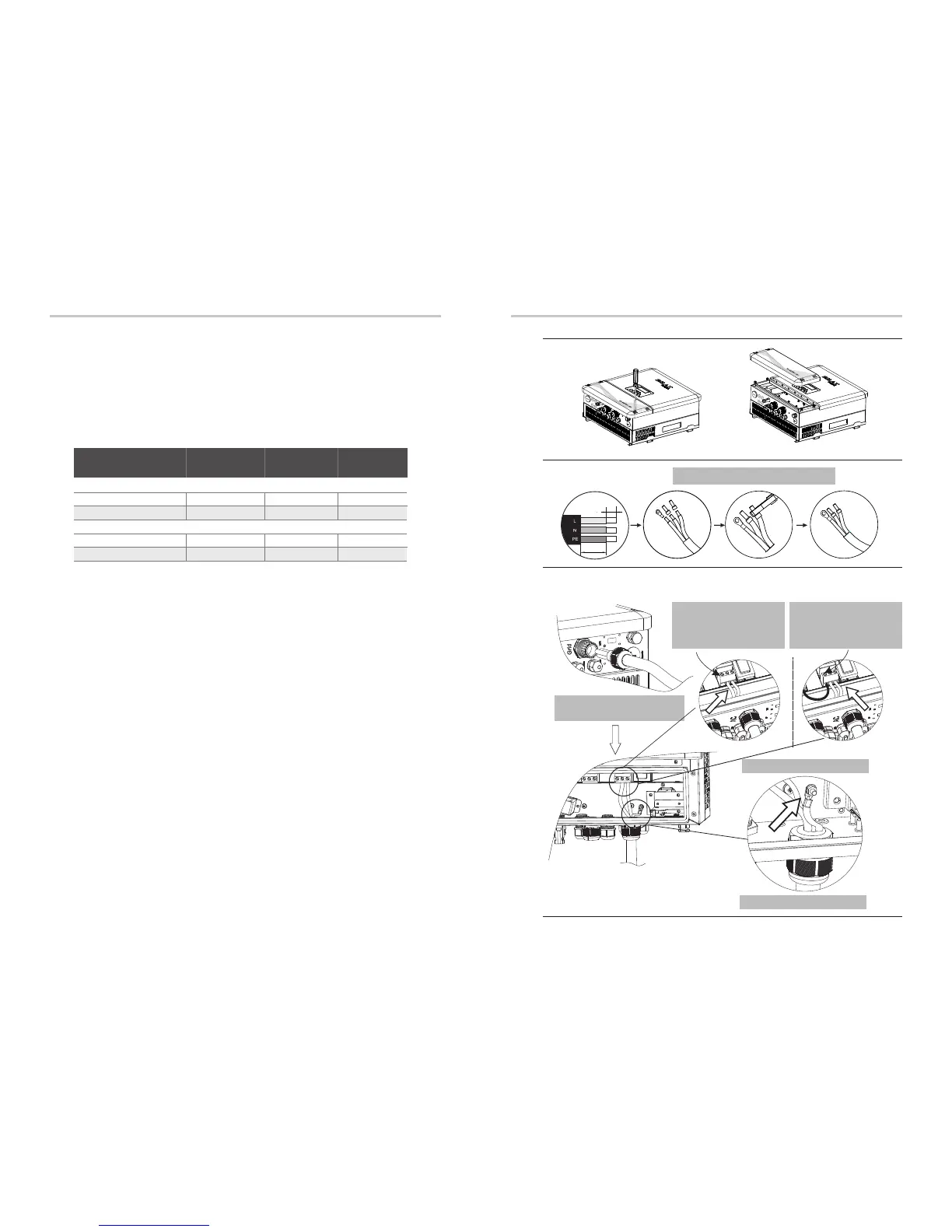
Step2. Remove the top-down cover from the inverter.
Step3. Make AC wires.
3.1 Choose the appropriate wire(Cable size: refer to Table 4).
3.2 Reserve about 60mm of conductor material sectional area.
3.3 Remove 12mm of insulation from the end of wire.
3.4 Insert stripped wires into AC terminal and insure all conductor strands are captured in the AC
terminal.
3.5 Compress the AC terminal head by using a crimping pliers and screw down screw cap tightly.
Step4. Insert AC cable into Grid port through screw cap and then tighten the
screw cap. Insert L wire and N wire into corresponding ports of AC terminal.
Compress the PE wire with earth terminal , then screw it on the grounding stud.
Cable
Micro-breaker
4-5mm² 5-6mm² 5-6mm²
20A 32A 32A
Model
Cable
Inverter+BMU
Micro-breaker
8-10mm² 10-13mm²
10-13mm²
50A 63A 63A
E Version & C Version
I Version
Electrical ConnectionElectrical Connection
22
6. Electrical Connection
X1-Fit-3.7E
X1-Fit-3.7I
X1-Fit-3.7C
X1-Fit-4.6E
X1-Fit-4.6I
X1-Fit-4.6C
X1-Fit-5.0E
X1-Fit-5.0I
X1-Fit-5.0C
PE wire connection
L-wire,N-wire connection
Insert AC cable into Grid port
through screw cap
Cable Size: Refer to Tabel 4(page 24)
Step2.
Step3.
Step4.
X
N L
60mm
12mm
23
I N L
Note: No need toconn-
ect wire on X port by
enduser!
I Version
E Version
Note:I port has been
wired during the
manufactory.
 Loading...


