7.2 Grid ports connection
Grid port connection of parallel box side
Grid port Connection is between parallel box and Grid distributionn box.
Grid port connection of Grid distribution box side
Grid port connection of grid distribution box side should be analyzed and operated
depending on eld wiring condition.
Here will not be discribed into details.
7.3 Back-up Load ports connection
Selecting appropriate Back-up loads
Load port Connection is between parallel box and Back-up Load.
• I version and E all need to connect 5 cables (R, S, T, N, G).
• R/S/T/G cables connection are the same, but N /P bar of I version and N/P bar of E
are different.
Before the system installation, user must project some important load as the back-up
loads which need to be worked when there is an outage.
When selecting back-up loads, the requirement shown as below must be satised:
1: Algebraic apparent power of back-up loads must be less than Algebraic apparent
power of hybrid system * 0.9.
2: Algebraic RCD apparent power of RCD back-up loads must be less than Algebraic
apparent power of hybrid system * 0.6.
For example:
If 1* X3-Hybrid-6.0-D-E inverter and 2*X3-Hybrid-10.0-D-E inverters are installed in one system,
the agebraic apparent power of hybrid system=1*6KW+2*10KW=26KW
the algebraic apparent power of back-up loads must less than 26kw*0.9=23.4KW.
If the back-up load is belongs to RCD nonlnear load, the algebraic RCD apparent power of
the loads must be less than 26KW*0.6=15.6KW.
• I version and E all need to connect 4 cables (R, S, T, N).
• R/S/T cables connection are the same, but N bar of I version and N bar of E are
different.
17
16
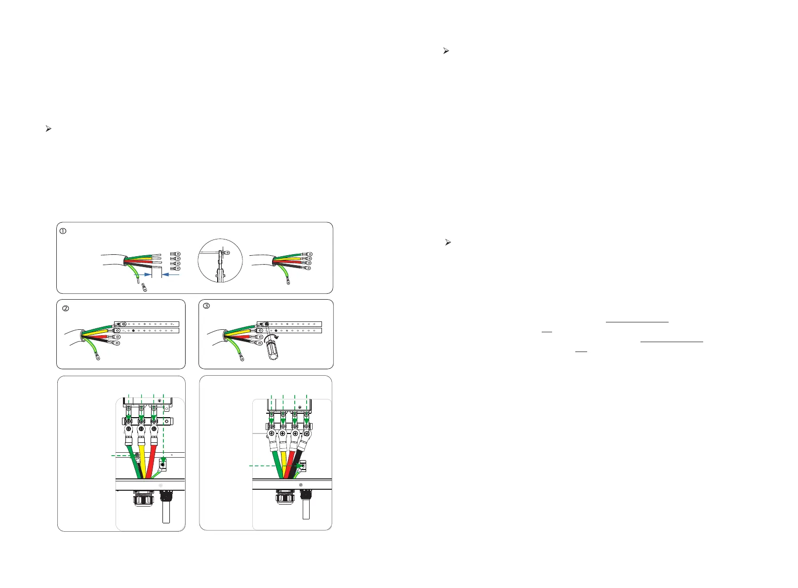
Step 1.Make Grid wire.
Select the right wire (cable size: see figure below).
Remove 10mm insulation from wire ends.
Insert the stripping terminal.
Press the terminal head with the blank holder.
Step 2.Screw through cable port and corresponding EPS ports (R-bar, S-bar, T-
bar, N-bar,G-bar) and tighten.
I version -N E version -N
T1 T2 T3
P
N
EPS
GRID
N
G
TS
R
P
EPS
GRID
T1 T2
T3
T4
NTS
R
G
Crimp!
10 mm
( 5.5-4 )
stripping terminal
P5 version 4WAG
P10 version 0WAG

 Loading...


