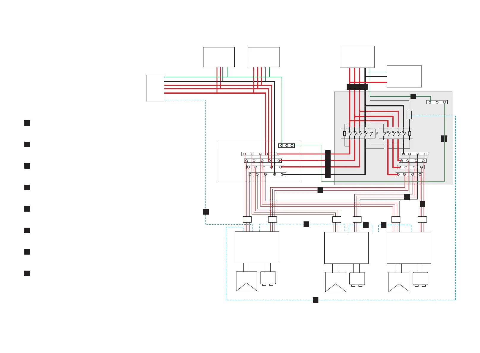
4 ALL Cable Connection Overview
F
Communication connection between parallel box and Master Inverter
(refer to Section 7.4, page 21)
EPS connection between Inverter and parallel box
(refer to Section 7.1, page 14)
A
Grid connection between Grid Distribution Box and parallel box
(refer to Section 7.2, page 16)
B
EPS Load connection between EPS load and parallel box
(refer to Section 7.3, page 18)
C
Earth connection between parallel box and external earth bar
(refer to Section7.2, page 16)
D
A large number of cables need to be connected in one parallel system.
Only cables marked with majuscule in below system diagram will be
introduced in this manual.
For other cables connection, here will not be discribed.
Communication connection between Inverters
(refer to Section 7.4, page 19)
G
E
Earth connection between parallel box and EPS Load
(refer to Section 7.3, page 18)
Communication connection between Master Inverter and SOLAX meter.
(refer to Section 8.2, page 23)
H
9
8
KM2
+ -
Battery
R-bar
S-bar
T-bar
N-bar
A1
A2
KM1
A1
A2
NC
NC
NC
NC
...
X3-Hybrid Inverter
Master
X3-Hybrid Inverter
Slave
... ...
CAN
Meter
CAN CAN CANCAN
I/O
EPS
GRID
EPS
GRID
PV+ PV-
+ -
Battery
PV+ PV-
+ -
Battery
PV+ PV-
three-phase
Backup Load
single-phase
Backup Load
PE
SOLAX
Meter
Grid
R
S
T
N
... ...
three-phase
common Load
single-phase
common Load
Breaker Breaker Breaker Breaker Breaker
R-bar
S-bar
T-bar
N-bar
Grid Distribution Box
X3-EPS
Parallel Box
...
...
...
...
...
...
...
R-bar
S-bar
T-bar
N-bar
PE-bar
PE-bar
EPS
X3-Hybrid Inverter
Slave
CAN
GRID
Breaker
A
A
H
A
B
C
D
E
F
G
G
G

 Loading...


