Load port connection of parallel box side
Grid port connection of Loads side
Grid port connection of loads side should be analyzed and operated depending
on specic loads.
Here will not be discribed into details.
7.4 Communication connection
The communication connection is between parallel box and hybrid Master Inverter.
In parallel system, one inverter will be set the “Master inverter” which will control
every other inverter’s energy management and dispatch control.
Note: For how to set a Master inverter, please refer to page 4.
Communication connection of Master inverter side.
19
18
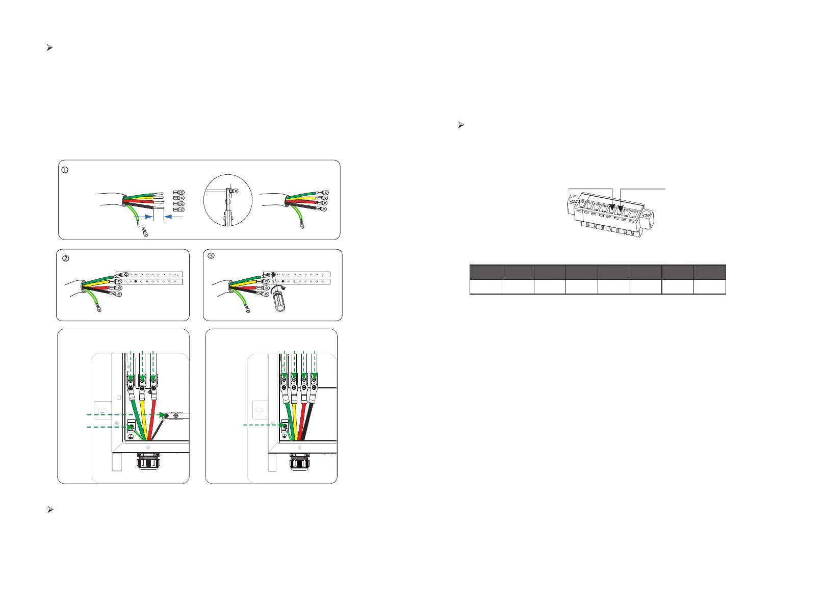
Step 1.Make Load wire.
Select the right wire (cable size: see figure below).
Remove 10mm insulation from wire ends.
Insert the stripping terminal.
Press the terminal head with the blank holder.
Step 2.Screw through cable port and corresponding EPS ports (R-bar, S-bar, T-
bar, N-bar,G-bar) and tighten.
E version -N
GEN_B
GEN_A
Shutdown
+3.3V
GND
485A
485B
1 2 3 4 5 6 7 8
EPS
Communication interface with the main inverter for EPS and GND, two wires.
Master inverter communication connection steps:
Ø
The steps of X3-EPS parallel box communication line connection of the main
inverter are as follows:
LOAD
L1 L2 L3
P
N
I version -N
T
S
R
N
G
N
L1
L2
L3
P
LOAD
R
S TN
G
R
S
T
N
G
I version -N
EPS(pin6)
GND(pin5)
Step3. Trip the insulation from the communication wires, then insert one side
of wires into pin1 and pin2 holes of the 8 pin positive terminal which can be
found in accessories package. And then screw them tightly.
Step4. Insert the positive terminal into the corresponding negative terminal block
inside of the inverter. And then screw it tightly.
Step1. Prepare a connector and two communication wires.
Step2. Unscrew the nut of EPS connector and insert two communication
wires through it.
Crimp!
10 mm
( 5.5-4 )
stripping terminal
P5 version 4WAG
P10 version 0WAG

 Loading...


