8 Connection of Parallel System
8.1 Master Inveter and Slaver Inveter
Hybrid
inverter
Hybrid
inverter
Master
Slave
Slave
Hybrid
inverter
SOLAX
Meter
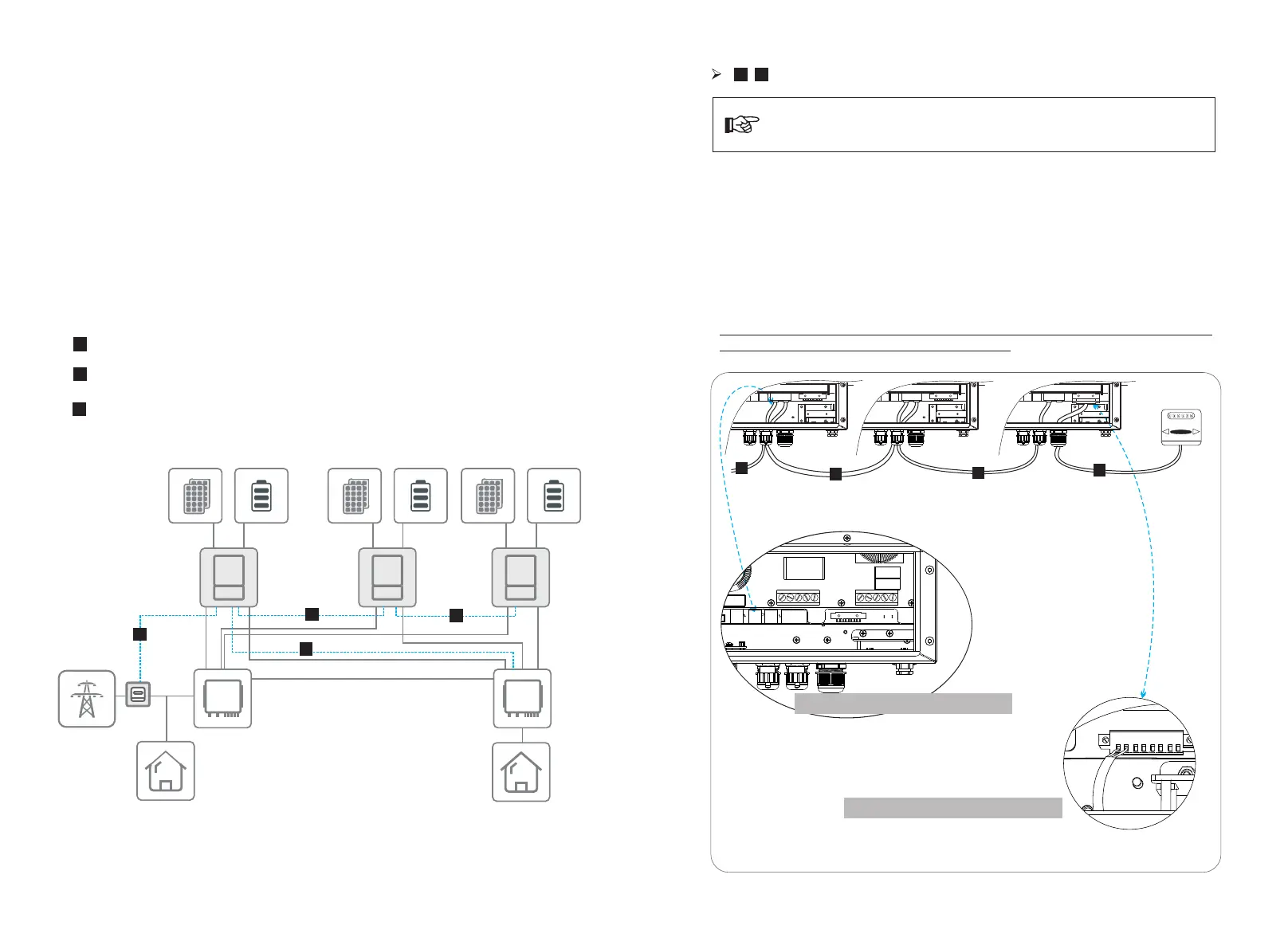
In parallel system, one inverter will be set as the “Master inverter” which will control
every other inverter’s energy management and dispatch control. Only one meter
needs to be connected in this system and communicate with the “Master inverter”,
and all other slaver inverter communicate with “Master inverter” by
CAN communication-parallel connection.
8.2 All communication connection of parallel system
B
C
A
Communication connection between Master Inverter and SOlAX meter
Communication connection between Inverters
Communication connection between Master Inverter and parallel box
(refer to page 19)
B
C
A
B
CAN-CAN connnection:
-Insert one side of CAT7 cable into the rst inverter’s CAN port and the other side into
the next inverter’s CAN port.
RS485-Meter connection:
- Insert one side of CAT5 cable into the RS485 port of meter, and the other side into the
COM 1 port of the rst inverter or the CAN 2 port of the last inverter.
Please note the inverter connected with meter will be the Master Inverter and this
Master inverter must be connected with battery.
Connection Steps
B
A
Note: Use standard CAT7 network cables for CAN-CAN connection and
CAT5 cable for CAN-Meter connection.
Meter Port: The first RJ45 port from left side
Note: For specic cable operation of these cables, please refer to Inverter User Manual
23
22
Grid
EPS
EPS
EPS
Load
Load
Grid
Grid
Grid
Grid
Grid
Grid
EPS
EPS
EPS
Grid
CAN
CAN
CAN Port: The first RJ45 port from left side
CAT5 cable
CAT7 network cablesCAT7 network cables
CAN-CAN CAN-CAN CAN-meter
Meter
CAN1 CAN2 CAN1 CAN2
CAN1 CAN2
B
B
B
A

 Loading...


