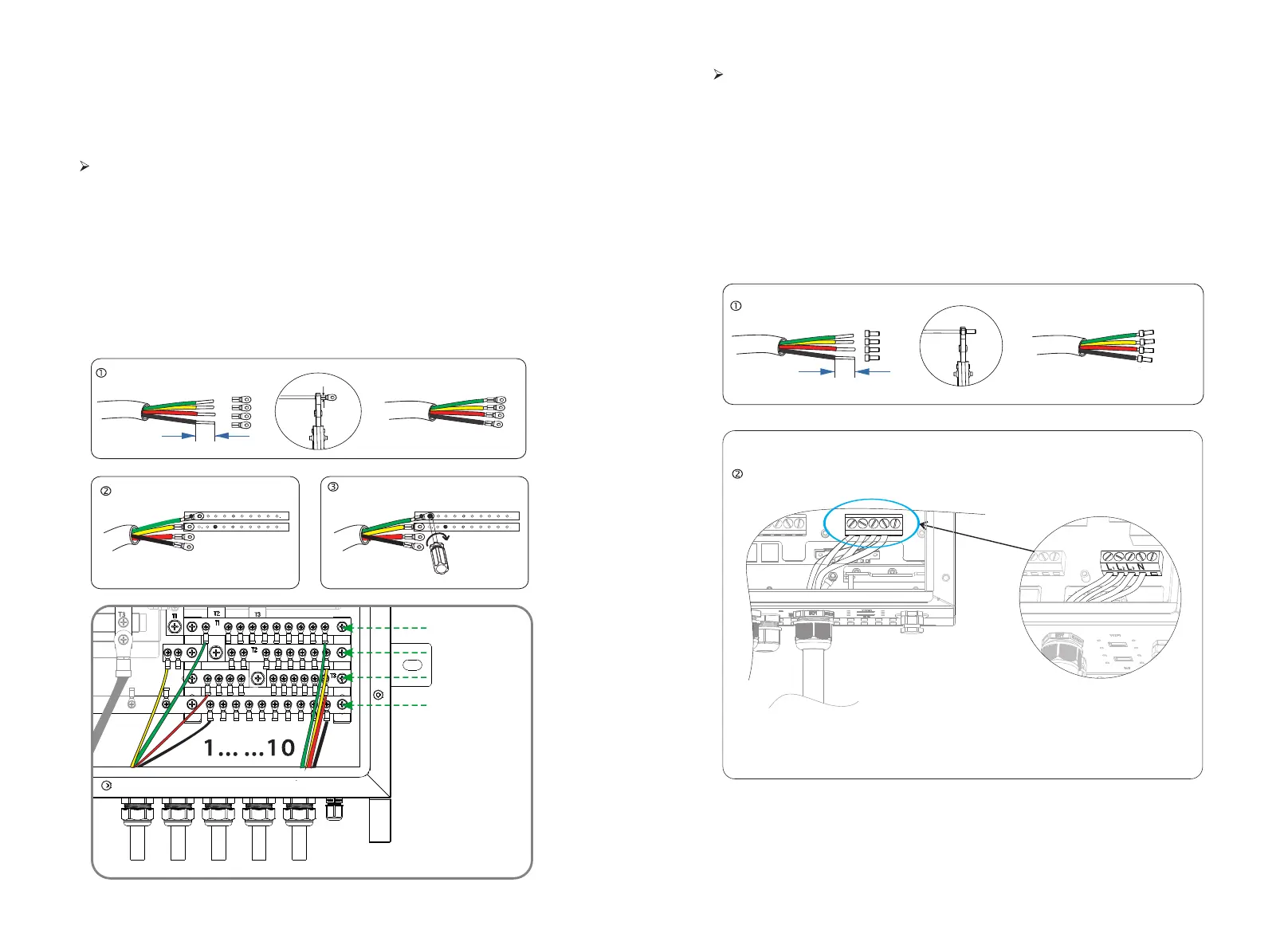
7.1 EPS ports connection
10 AWG
10 mm
Crimp!
( 5.5-4 )
R-bar
S-bar
T-bar
N-bar
EPS port connection of parallel box side
EPS port Connection is between parallel box and hybrid inverters.
• EPS port Connection of I version and E version are the same.
EPS port connection of inverter side
Step1.Make EPS wires.
Choose the appropriate wire(cable size: refer to picture below).
Reserve about 60mm of conductor material sectional area.
Remove 12mm of insulation from the end of wire.
Insert stripped wires into AC terminal.
Compress the AC terminal head by using a crimping pliers and screw down screw cap tightly.
Step2. Insert EPS cable into EPS port through screw cap and then tighten the screw
cap. Insert L1,L2,L3 wire and N wire into corresponding ports of EPS terminal and
screw them tightenly.
10 AWG
10 mm
Crimp!
Step 1.Make EPS wire.
Select the right wire (cable size: see figure below).
Remove 10mm insulation from wire ends.
Insert the stripping terminal.
Press the terminal head with the blank holder.
Step 2.Screw through cable port and corresponding EPS ports (R-bar, S-bar, T-
bar, N-ba) and tighten.
15
14
PE
L1 L2 L 3 N

 Loading...


