There is an RS485 port on the bottom of the inverter. Through this port, the
inverter can 1) communicate with the computer, Datahub or other devices and
the meter and achieve the parallel function or EV-Charger function; or 2)
achieve multiple functions like DRM (Demand Response Management), dry
contact function and heat pump control via Adapter Box.
RS485 port of
the inverter
USB port of the
computer
RS485 to USB
• RS485 Connection Steps:
1. Prepare RJ45 connector and a communication cable.
2. Strip the insulation from the communication cable.
3. Let the communication cable pass though the waterproof connector with
RJ45, then insert it into the RJ45 connector following the PIN definition rule.
Hand tighten. torque: 1.2±0.1 N·mHand tighten. torque: 1.5±0.1 N·m
4. Crimp the RJ45 connector with the crimping plier.
5. Insert the cable into the RS485 port of the inverter, and tighten the
waterproof connector.
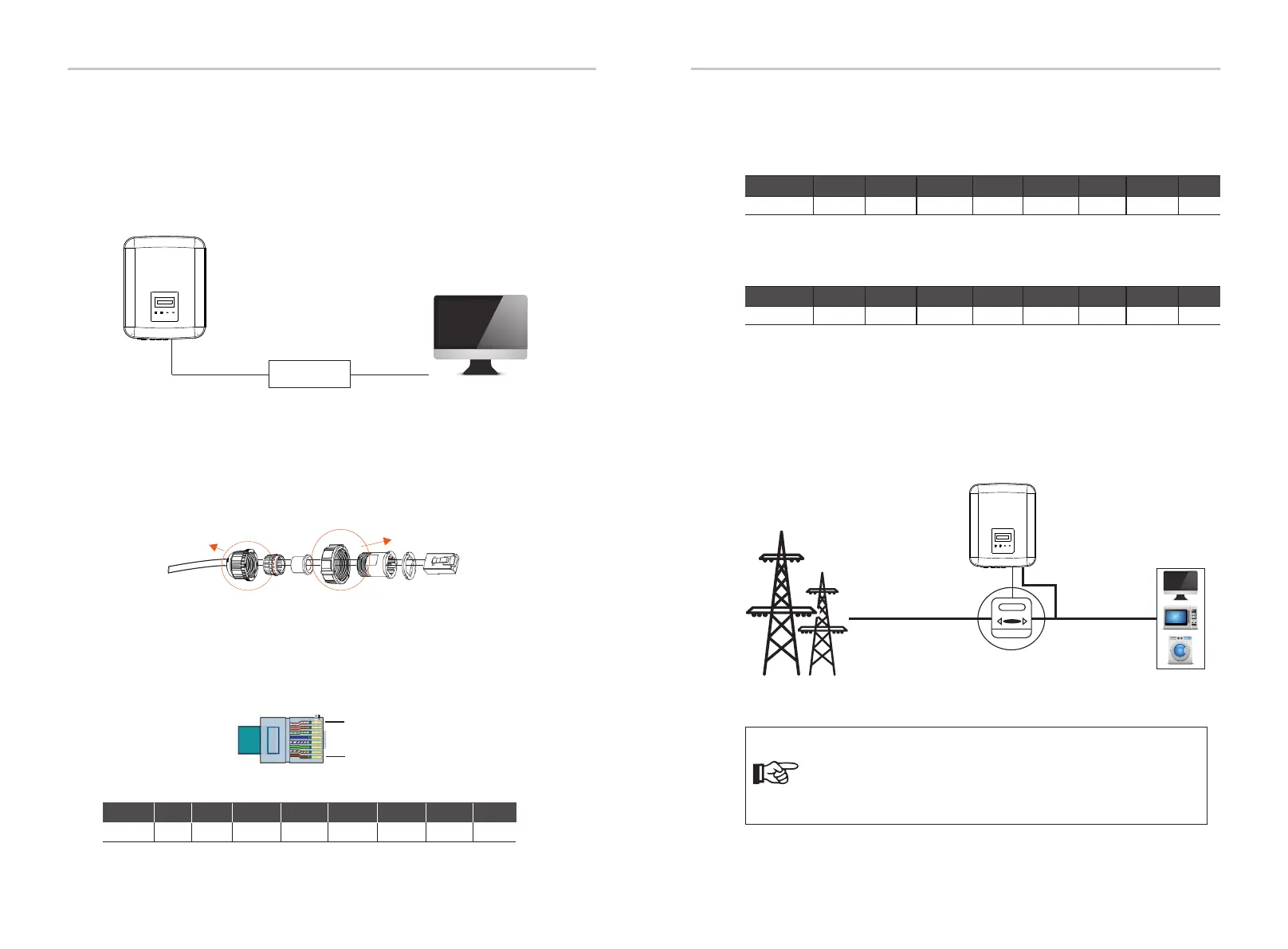
6.4.2.1 Meter Connection (Optional)
1. Monitor the energy to grid and from grid throughout the whole day.
2. Achieve the export control function with a higher accuracy.
The inverter can communicate with a meter through this interface, with the
meter you can:
The smart meter must be authorized by us, any third party or
non-authorized meter may not match with the inverter.
We will not take the responsibility if the unauthorized meter is
unavailable.
Please see the Quick Installation Guide for three-phase meter for details.
Meter Connection Steps:
Note!
a) The PIN denitions of RS485/Meter interface are as below.
1
8
PIN
Definition
1 2 3 4 5 6 7 8
485_A
X
485_B
X X
Electrical
grid
Electric meter,
bidirectional
Loads
Inverter
X
6.4.2 RS485/Meter Connection
• PIN Definition:
X X
b) DRM is provided to support several demand response modes by giving
control signals as below.
Pin
Definition
1
2
3 4
5
6
7
8
DRM0
XX X X X
+12V
X
Pin
Definition
1
2
3 4
5
6
7
8
X
Heat Pump
X X GND X
c) Heat Pump Controller is the controlling signal provide by the inverter to
switch on or off the SG ready heat pump via Adapter Box. The PIN definition is
as below:
X X
Electrical Connections Electrical Connections
28 29

 Loading...


