Mains cable (AC line cable) shall be short-circuit protected and thermal overload
protected.
Always fit the input cable with fuse. Normal gG (US: CC or T) fuses will protect the
input cable in short circuit situation. They will also prevent damage to adjoining
equipment.
Dimension the fuses according to local safety regulations, appropriate input
voltage and the related current of the solar inverter.
AC output protected by external fuse (gG rated current 16 A/600 VAC for X3-MIC-
3K-G2/X3-MIC-4K-G2/X3-MIC-5K-G2/X3-MIC-6K-G2; 25 A/600 VAC for X3-MIC-5K-
G2-LV/X3-MIC-8K-G2/X3-MIC-10K-G2; 40 A/600 VAC for X3-MIC-6K-G2-LV/X3-
MIC-8K-G2-LV/X3-MIC-12K-G2/X3-MIC-15K-G2) provides in all live connections to
the AC supply.
The rated short-circuit breaking capacity of the above protective device shall be
at least equal to the prospective fault current at the point of installation. See
section technical data of this manual for details.
2 2
AC output cable: Cu; R, S, T, N+PE: 3*4.0 mm +4.0 mm for X3-MIC-3K-G2/X3-MIC-
2 2
4K-G2/X3-MIC-5K-G2 and 3*5.3 mm +5.3 mm for X3-MIC-5K-G2-LV/X3-MIC-6K-
2 2
G2/X3-MIC-8K-G2/X3-MIC-10K-G2, 3*6 mm +6 mm for X3-MIC-6K-G2-LV/X3-MIC-
8K-G2-LV/X3-MIC-12K-G2/X3-MIC-15K-G2 @40 ambient temperature.℃
Selection of Fuses and Cables
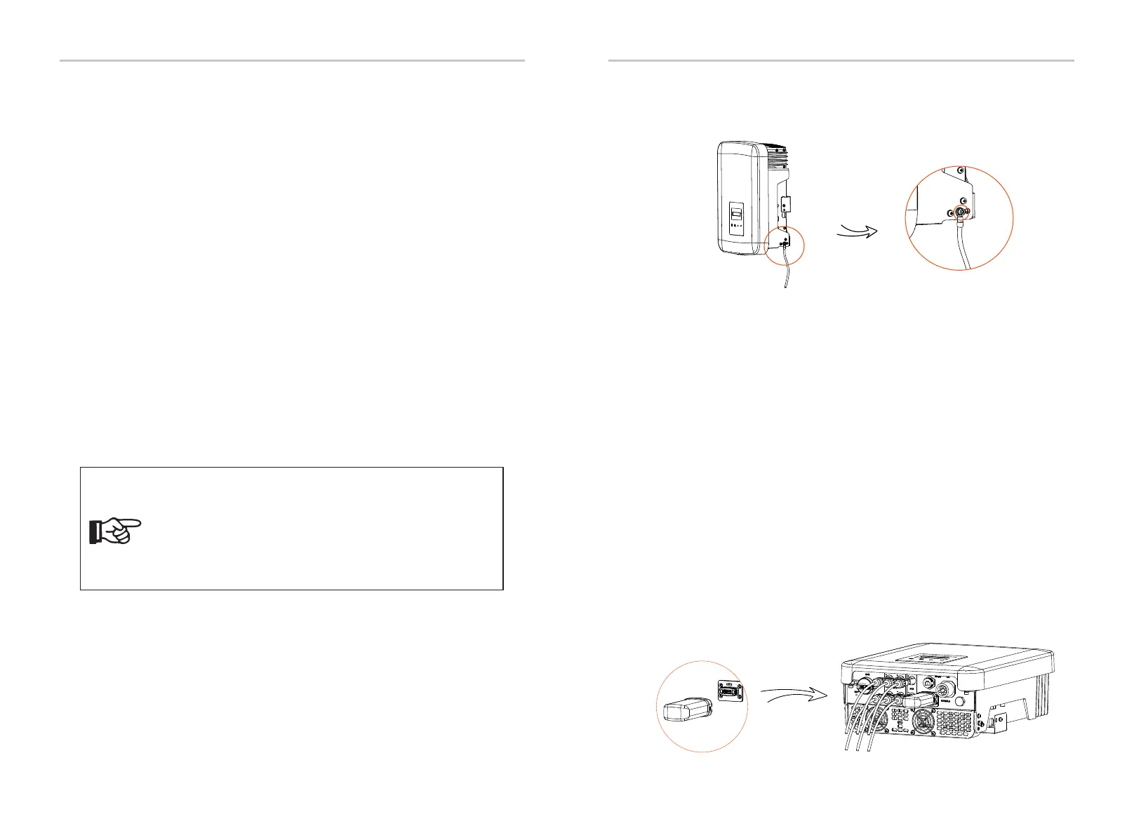
Screw allen wrench the ground screw with the shown as follows.
This product has a series of communication interfaces: such as WiFi,
RS485/Meter, DRM and USB for upgrading for human and machine
communication. Operating information like output voltage, current,
frequency, faulty information, etc., can be delivered to PC or other
monitoring equipment via these interfaces.
6.4.1 Monitoring Connection (Optional)
This inverter provides a monirtoring dongle connecting port (the DONGLE
port) which can collect information from inverter including status,
performance and updating information to the monitoring website via
connecting WiFi/LAN/4G dongle (The monitoring dongle is optional, which
can be purchased from the supplier if needed).
Connection steps(Take WiFi dongle as an example):
1. Plug the WiFi dongle into “DONGLE” port at the bottom of the inverter.
2. Connect the WiFi with router.
3. Download the monitoring APP for setting up.
4. Follow the steps to create a new account, set up internet connections
and check the inverter status.
(For more details of the monitoring configuration, please refer to the WiFi
/LAN/4G dongle user manual in the box.)
torque: 1.2±0.1 N·m
Therefore the current-carrying capacity of the components and sub-assemblies
provided in the end-use system(connectors, cables, junction box, switchgear,
etc.) and the reverse current PV modules shall be considered based on the
feedback current and reverse current. The direct current(DC) circuit breaker or
fuse between each solar generator and inverter shall be provided based on
solar inverter input ratings.
Select DC cables based on the above inverter back-feed current and ISC PV
rating and Vmax ratings.
1. For condition differing from those mentioned above,
dimension the cables according to local safety regulations,
appropriate input voltage and the load current of the unit.
(You can choose a thicker cable but the fuses must be rated
according to the rating of the cable.)
2. Fuses must be approved by Notified Body.
3. The AC output cable would be better to use the soft wire.
Note!
Electrical Connections Electrical Connections
6.3 Earth Connection
6.4 Communication Connection
26 27

 Loading...


