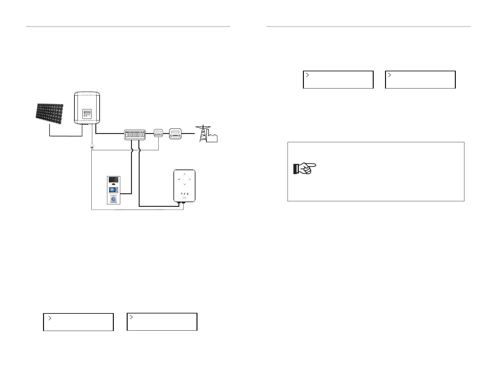
6.4.2.3 EV-Charger Function
The inverter can communicate with the smart EV-Charger to form an
intelligent photovoltaic, storage and EV charging energy system, thus
maximizing the utilization of photovoltaic energy.
a) Prepare an RJ45 splitter and the splitter should be placed in a waterproof
place.
b) Connect the communication cables of the EV-Charger, the meter and the
inverter via the splitter following the PIN definition rules.
c) The communication cable connected with the inverter should be plugged
into the RS485 port of the inverter.
Ÿ Wiring operation
Turn on the power of the entire system, enter the “Settings” page of the
inverters on the LCD screen.
a) Enter the “Export Control” page and choose “Meter”.
Ÿ LCD setting
Mode Select
Meter
Export Control
DRM Function
Diagram: Intelligent Photovoltaic, Storage and EV Charging Energy System
Modbus Function
Function Select
EV Charger
b) Enter “Modbus Fuction” and select “EV Charger”.
c) Set the “Grid Data Source” as “Inverter” in the APP of the EV-Charger.
For the installation and settings of the EV-Charger, please refer to the user
manual of the EV-Charger for details.
Note!
The EV-Charger function and the parallel system with Datahub
cannot be used at the same time currently.
If the EV-Charger function is enabled and Datahub is
connected in the system, please remove the Datahub, then
the EV-Charger will work normally. If the Datahub is to be
remained in the parallel system, remove the Datahub first and
change “EV Charger” to “COM485” under the “Modbus Fuction”,
then reconnect the Datahub.
Electrical Connections Electrical Connections
32 33
Electrical
grid
PV array
AC distribution box
Inverter
Electricity meter,
bidirectional
Meter
Splitter
485A & 485B
Meter cable
RS485 cable
Loads
EV-Charger

 Loading...


