68
Electrical Connection
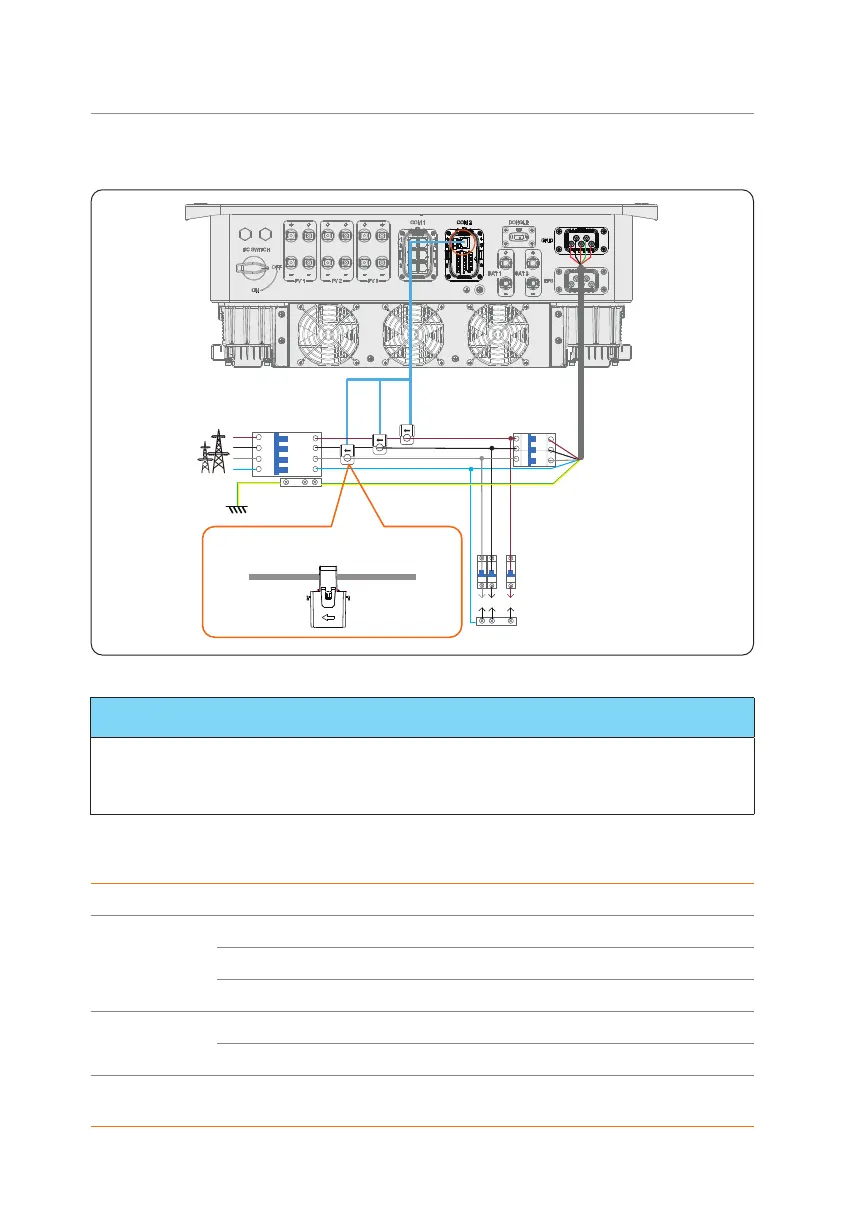
• CT connection diagram
CT-RCT-SCT-T
L1
L2
L3
N
Grid
The arrows direction on the CT must point
to the public grid side.
Inverter
Loads
N-BAR for loads
CT
Grid
E-BAR
Breaker
Breaker
L line
…
…
Figure 8-46 CT connection diagram
NOTICE!
• The arrow on the CT must point at the public grid.
• CT-R must be connected to L1, CT-S connected to L2, and CT-T connected to L3 in
accordance with the L1, L2 and L3 of the inverter's Grid terminal.
Meter/CT pin definition
Pin Pin assignment
For CT
connection
1 CT_R1_CON
2 CT_S1_CON
3 CT_T1_CON
For Meter
connection
4 METER_485A
5 METER_485B
For CT
connection
6 CT_T2_CON

 Loading...


